


 Mean Stack Development
 Vue JS Development
 Javascript Development
 React JS Development
 Angular JS Development
 Next JS development
 Java Development
 Python Development
 Django Development
 Cherrypy Development
 C# Development
 ASP.NET Development
 NodeJS Development
 Laravel Development
 CodeIgniter Development
 Zend Development
 Ruby on Rails Development
 CakePHP Development
 PHP Website Development
 Symfony Development
 Drupal Development
 Joomla Development
 Wordpress Development
 .NET Nuke Development
 Kentico
 Umbraco
 .NET MAUI Development
 Xamarin Application Development
 iOS Application Development
 Android Application Development
 Android Wear App Development
 Ionic Development
 iBeacon Application Development
 Universal Windows Platform (UWP)
 Kotlin Application Development
 Swift Application Development
 Flutter Application Development
 PWA Application Development
 Flutter Health Tech & Wearable App Development Company
 React Native Health Tech Wearable App Development
 Offshore Software Development
 Custom Application Development
 Front-End Development
 Full Stack Development
 AI & Machine Learning
 Custom CRM Solutions
 Flask Software Development
 Electron JS Development
 ChatGPT Development
 Veterinary Telemedicine App Development
 Build Smart Telemedicine Platform
 Beauty & Salon App Solutions
 Hire Workato Experts
 Magento Development
 Magento 2.0 Development
 Magento Enterprise
 Shopping Cart Development
 Prestashop Development
 Shopify Development
 Open Cart Development
 WooCommerce Development
 BigCommerce Development
 NopCommerce Development
 Virto Commerce Development
 AspDotNetStorefront Development
 .NET Application Development
 Microsoft Dynamics CRM
 VB .NET Development
 Sharepoint Migration
 ASP.NET Core Development
 ASP.NET MVC Development
 AJAX Development
 Agile Development
 Microsoft Bot
 Microsoft Blazor
 Microsoft Azure Cognitive
 HTML 5
 UI/UX Design
 Graphic Design
 Adobe Photoshop
 XML Application Development
 Cloud Computing Solutions
 Azure Cloud App Development
 AWS Development
 Google Cloud Development
 Certified AWS IoT Services Developers
 DevOps Consulting & Development
 Kubernetes Consulting & Services
 SQL Programming Development
 MySQL Development
 MongoDB Development
 Big Data
 Robotic Process Automation
 Social Media Marketing
 Search Engine Optimization
 QA Testing
 Software Testing
 Software Security
 Maintenance And Support
 I.T. Consulting Services
 Business Intelligence
 YII Development
 Data Analysis
 Alexa Skills Development
 On Demand App for Mobile repairing services
 On Demand App for Car Service Booking
 On Demand App for Cleaning Services
 On Demand App for Pharmacy
 On Demand Dedicated Developers
 On Demand Lawyer App Development


 Nuki Smart Lock
 Salto Smart Lock
 TTlock Smart Lock
 NFC App Development
 Custom IOT Enabled Smart Lock
 Smart Locker Solutions
 Hospital Smart Lock Systems
 Hotel Smart Lock Systems
 Smart Home & Office Locks
 Smart Access for Schools & Colleges
 Unloc Smart Lock Integration
 Yale & August Smart Lock Integration
 Populife Smart Lock Integration
 Smart Lock Hardware Development
 Dairy IoT Solutions
 Agri IoT & AI Solutions
 Weather & Climate Solutions
 Water & Waste Management Solutions
 RaspBerry Pi
 Firmware Software Development
 ESP 32 Software Development
 Embedded Development
 Internet of Things
 Smart IoT Development
 IoT Sensor Integration & Development Solutions
 Smart IoT System Development for HVAC
 Tuya IoT App Development
 Particle IoT SDK
 IoT Development with AI
 Smart Pet GPS Tracker
 Dairy GPS Tracking Solutions
 GPS Fleet Management Software
 Car Rental & Subscription Solutions
 Car Buy & Sell Marketplace Development
 AI-Powered Car Wash App Development
 PCB Design & Fabrication
 IoT AC Automation
 AI–IoT Painting Solutions
 IoT Wearable Hardware & App Development
 HVAC Automation & AI Control Systems
 Smart Home IoT Engineering
 AI Embedded Systems
 AI Hardware Design Service
 Advanced IoT Hardware & Firmware Development
 Device Driver Development Services
 NXP i.MX RT Firmware & Hardware Services
 Microchip PIC & AVR Development
 Hire IoT Architects
 IoT Cloud & Infrastructure Solutions
 Infineon XMC / AURIX Development Services
 Matter & Thread IoT Services
 Native IoT Mobile App Development (BLE & Wi-Fi)
 Snapdragon IoT Firmware Development
 Renesas RA/RX Firmware Services
 Silicon Labs EFR32 Development Services
 Smart Wearable App Development
 Smart IoT Meters
 Smart Healthcare Wearable App Development
 Health Care Monitoring System
 Fitness Tracking App Development
 Smart Home Automation Apps
 nRF PCB Design
 ESP32 PCB Design
 Embedded Wearables Engineers
 Rental Property Management System
 Building Management System
 Smart Lighting Development
 Infineon Semiconductor Firmware Development Services
 Custom Camera Development: Hardware, Firmware & PCB Prototyping
 Smart Security Camera SDK
 Nordic Semiconductor SDK
 Infineon SDK
 Arduino SDK
 NFC Lock Integration
 Kerong Lock Integration
 IoT & AI Solutions for Manufacturing
 Smart Inventory & Logistics Solution
 Food & Beverage Industry Solutions
 Smart Hospitality Solutions
 Smart Property Management
 Custom Smart Home IOT SDK
 Smart IoT & AI in Healthcare
 AI-Powered Security Solutions
 Smart Home Safety & AI
 Veterinary Clinic Management (AI)
 Pet Care System (AI & IoT)
 Pet Training & Adoption (AI)
 Healthcare IoT Development
 Event Management Software
 Money Remittance App
 Money Lending App Development
 Utility and Bill Payment App
 IoT Mobile App Development (Flutter & React Native)
 AI & IoT Retail Solutions
 Smart EV App Development
 Smart Solar IoT & AI Solutions
 IoT-Based Energy Systems
 Smart Energy & Utilities Solutions
 6G Solutions
 IoT Security Solutions
 AI-Powered Lottery App Development
 AI-Sports Fitness Club Management
 Travel
 Real Estate
 Medical & Healthcare
 e-Learning
 Consumer Products
 Finance
 Automobile
 Media & Entertainment
 Billing Software
 Enterprise Resource Planning (ERP)
 Augumented & Virtual Reality
 Point of Sale(POS) Development
 Learning Management System
 EV Charging Solutions
 About Us
 Partners & Certifications
 Quality Assurance
 Our Clients & Testimonials
 Development Process
 Our Products
 Social Responsibility
 Work Ethics
 Vision & Mission
 Awards
 Live Project Demos
 Contact Us
 Case Studies
 Portfolio
 Blog
Medical Wearable Rigid-Flex PCB Design Services | Compact, Reliable Health-Tech Hardware
The design of wearables for the medical industry requires packing in advanced electronic components into devices that are lightweight and dependable. Irrespective of whether the device is a heart rate monitor, a smart patch, a sleep monitor, rehab sensor, blood sugar level monitor attachment, hearing aid or patient safety wearable, conventional rigid PCBs may bring about unnecessary restrictions in terms of size, connectors and reliability.
There is a more effective solution in the form of rigid-flex PCB technology. It involves combining rigid parts of the circuit where processors, batteries, sensors and connectors reside with flexible parts that can flex around the body or in an enclosure.
If done right, rigid-flex PCB design is able to minimize wiring, increase comfort of the product, simplify manufacturing and improve the reliability of the wearable electronics structure.
However, if not implemented effectively, rigid-flex design may lead to cracked conductors, unreliable signal paths, low yield, complicated assembly and costly re-design of the board.
Adequate Infosoft offers medical wearable rigid-flex PCB design services to health-tech companies, manufacturers, start-ups and researchers.
We design compact electronics that consider sensitive analogue signals, battery life, BLE connectivity, mechanical bending, manufacturability and integration with firmware, mobile applications and cloud platforms.
Let's Work Together!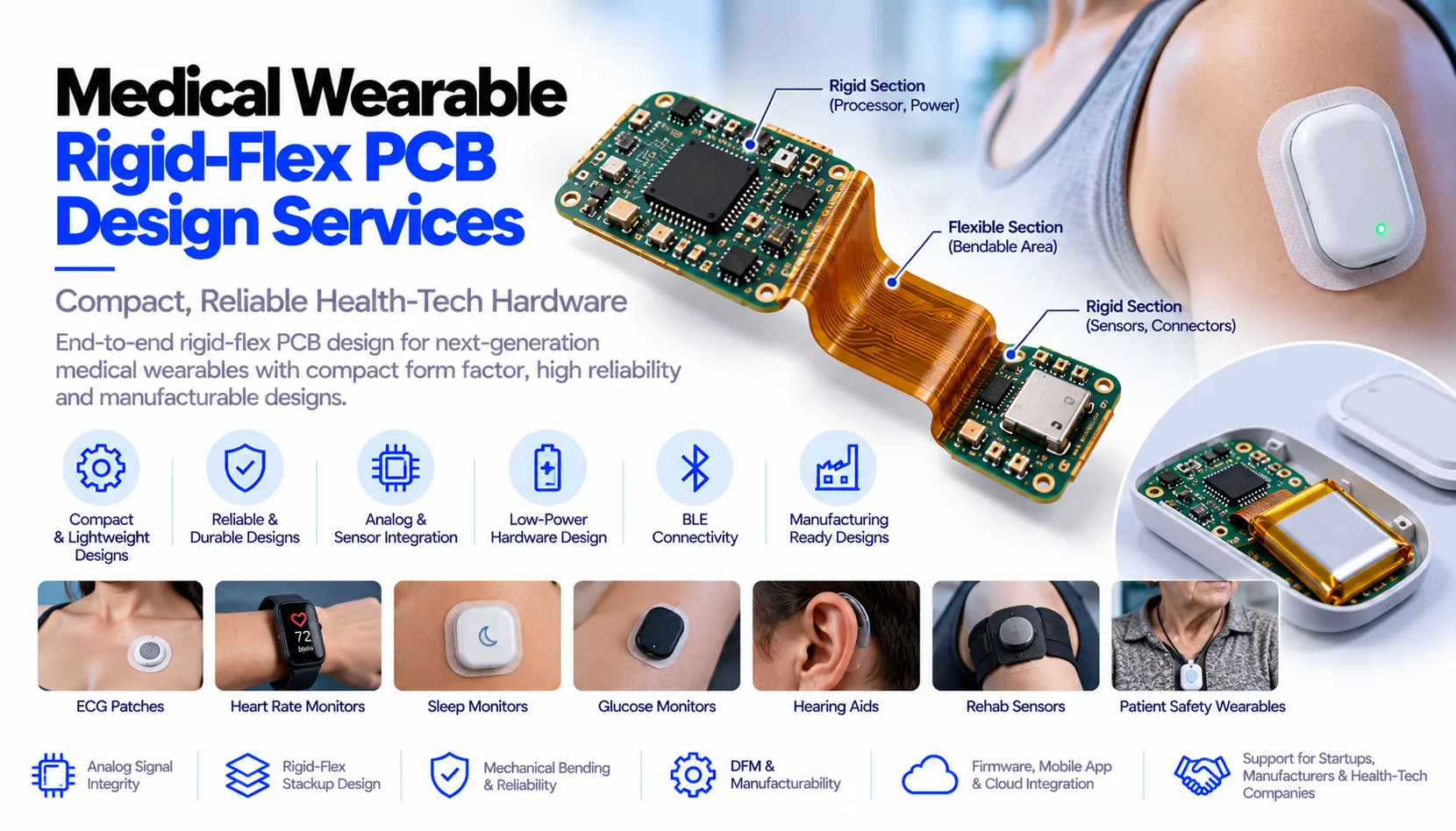
Why Rigid-Flex PCB Design Matters for Medical Wearables
Wearable technology does not comprise of just a small printed circuit board enclosed in a plastic enclosure. The circuit board could be designed to flex to wrap around the wrist, stick to the chest, rest behind the ear, be enclosed in a ring, and have connections to several sensors in a piece of clothing. Electronics need to be reliable while the user moves, sweats, charges the electronics, and wears it.
The use of rigid-flex design can minimize the requirement for separate rigid boards interconnected using wires or interconnections. The flexible part of the circuit can transfer the power and signals between the rigid parts of the circuit according to the mechanical form of the device.
Benefits of using rigid flex in medical/healthcare oriented products may include:
Reduced size of the end product Increased comfort to wear Minimal connectors and cable assemblies Better incorporation of sensors, batteries and antennas Better assembly in limited space Better reliability with respect to bending of the device Greater flexibility in designing multi-sensor devices
But the rigid flex isn't always an optimal choice for all projects. The stack up of materials, bend radius, copper thickness, orientation of traces, stiffeners, components location and assembly procedure have to be chosen based on the form factor of the final product.
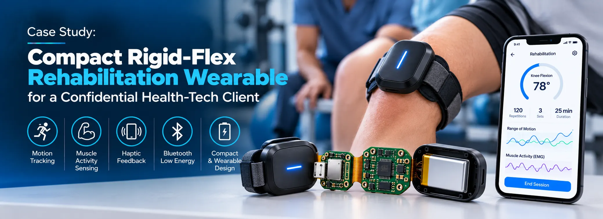
Case Study: Compact Rigid-Flex Rehabilitation Wearable for a Confidential Health-Tech Client
Client Requirement
HealthTech startup company contacted Adequate Infosoft to help design the compact wearable device for physical therapy and motion tracking. It had to fit comfortably around the joint, record the motion and muscle activity data, vibrate, and send the data of the session to the dedicated mobile application of the clinician.
At the first stage of design, two small rigid PCBs connected with a wire were supposed to be developed. However, this approach was bulky, uncomfortable to fit into the soft wearable case and prone to damage from constant movement. The task was to replace this design with the one using the rigid-flex technology.
Rigid-Flex Hardware Architecture
Two sections of a rigid PCB board have been designed along with an interconnection via the flexible region. The first section consisted of low-power MCU for Bluetooth operation, battery charger, memory and the antenna. The second section contained the sensor interface circuit, IMU and haptics driver circuit. The flex zone enabled the electronics to be fitted in accordance with the curve of the physical design, but the heavier elements were kept at a distance from the bend region.
As far as the muscle sensing region is concerned, the circuit layout has been performed in such a way that the analogue traces are physically separated from the clocks, radiations and haptics path carrying high currents.
The flex traces were routed with bend behaviour in mind, avoiding unnecessary vias and sharp routing transitions in the area expected to flex during wear. We worked with the mechanical design team on bend radius, adhesive support and strain-relief features to reduce repeated-stress risk.
Outcome and Future Product Path
The rigid-flex design simplified the wiring of the device's internal electronics while better integrating the enclosure. It also provided a platform that could accommodate changes in the size of the strap as well as different sensor arrangements without requiring redesigning the whole electronic system.
The firmware was designed to allow scheduling sensor readings, BLE synchronization, battery level reading and haptic feedback. All this resulted in a more robust prototype design base, which included documentation for future validation and manufacturability.
Relevant Adequate Infosoft Experience
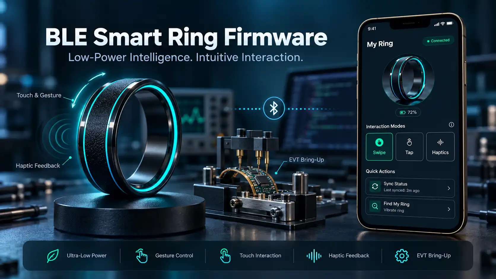
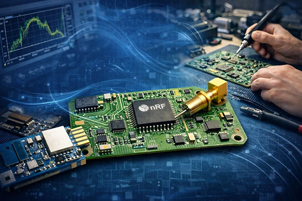
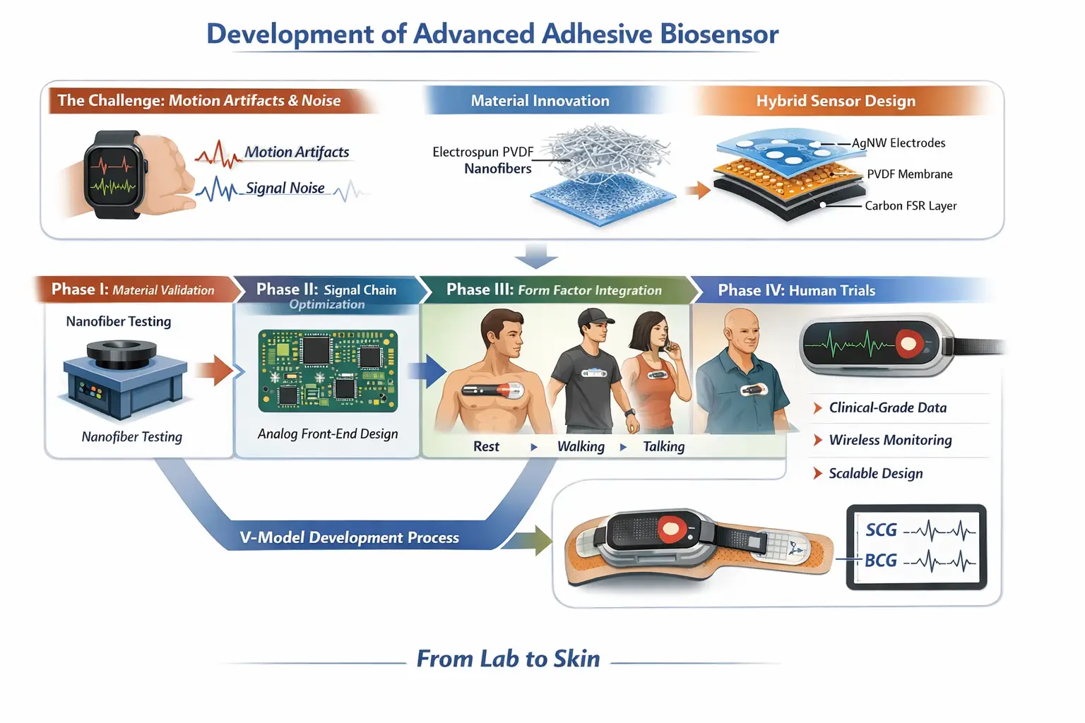
Adequate Infosoft has delivered embedded, wearable, healthcare and connected-device projects that support the skills needed for medical wearable rigid-flex development.

Our Medical Wearable Rigid-Flex PCB Design Capabilities
Compact Electronics Architecture
We collaborate with product development teams to translate requirements into a realistic board architecture. This involves locating the electronic components in the rigid sections of the design and limiting the flex to only those sections where it provides value.
Examples of rigid sections include the microcontroller, battery management system, wireless SoC, display connector, charging pins, and memory/sensor analog front-end.
Examples of flex sections include a skin-contact sensor, optical PPG sensor, electrodes, buttons, secondary battery location, or any other rigid PCB section.
Architecting the board in early stages is important since relocating critical components such as a battery, antenna, or an analog circuitry after the mechanical design is set becomes very expensive.
Low-Noise Biosignal and Sensor Layout
Most medical and health devices capture small signals such as ECG, EMG, EEG, PPG, temperature, motion, pressure, or impedance signals. Designing these requires a proper approach to decoupling sensitive analogue signals from sources of noise such as radios, DC-DC converters, displays, charging circuits, and fast clocks.
Our team assists in positioning of the analogue front end, short input signal routes, grounding issues, power decoupling, shielding of sensors, and return paths. If the product is intended to use Bluetooth Low Energy, we will take care of positioning of the antenna and the RF keep-out area.
For optical devices, we also consider LED-driver routing, photodiode paths, ambient-light interference and thermal effects. Good layout cannot eliminate every motion artefact or physiological variable, but it provides a cleaner foundation for firmware filtering and signal-quality algorithms.
Flex Design for Bend Reliability
The flex region needs to be designed considering how the product is going to move. Flex circuits which bend just once while assembling a product will behave differently than flex circuits that bend multiple times when wearing a wrist band.
We discuss Static vs Dynamic bending, bend radius, copper weight, number of layers, orientation of traces and if stiffeners are needed. The routing of traces in the bend region avoids acute angles, and important traces are placed based on mechanical stress. We also try to keep away components, vias and pads from the bend region unless the design supports them.
We work with mechanical engineers for enclosure clearances, adhesive locations, strain relief and battery locations. It prevents a very good mechanically looking industrial design from imposing mechanical stress on the PCB.
BLE, Power and Charging Integration
The wearable devices used in medical devices usually integrate an MCU, a BLE radio, a battery, a charge circuitry, and several sensors. Our hardware engineering team specializes in providing hardware design support for Bluetooth communication, battery management, fuel gauging, USB-C or wireless charging, protection circuitry, and low-noise power delivery.
Our power architecture is critical to biosignal device design. The switching charger or the radio burst may introduce measurement noise if it is positioned inappropriately or routed incorrectly. We take into account the peak current draw, sleep current, battery life, safety of the charging, decoupling, and power states in the firmware.
DFM, DFT and Manufacturing Support
There are certain factors that come into play when rigid-flex fabrication is being considered, which are not involved in two-layer rigid board manufacturing process. We consider all these aspects in our design while making preparation for fabrication and assembly.
We also design for test. Production teams need accessible test points, programming connections, calibration steps and traceability information without compromising the compact form factor.
Our deliverables can include schematic files, layout files, Gerbers or ODB++, BOM, pick-and-place data, assembly drawings, stack-up notes and manufacturing documentation.
Our Rigid-Flex PCB Design Process
Requirements of Medical Device and Design Planning
Each design starts from the end-use, wearability, skin-contact issues, bending considerations, battery duration, and sensor and data transfer requirements. Our design team examines industrial design files, enclosure sizes, component restrictions, and sensor placements to define the board architecture.
PCB Board Layout and Multidisciplinary Coordination
We plan rigid and flexible areas, layer structures, critical routing, and component placements for our PCB designs. As we implement the PCB layout, we verify its performance through the analysis of signal integrity, power integrity, RF integrity, analogue routing, bend areas, clearances, and manufacturing processes.
Verification and Regulatory Considerations
Product-specific verification, risk management, and compliance requirements are considered through development. Product certification, validation, and approval are still subject to the proper process for the target market and product claims.
Why Choose Adequate Infosoft for Medical Wearable PCB Design?
The development of rigid-flex wearables goes beyond the mere ability of laying out circuits. It requires engineers who comprehend the relationship between electronics, mechanics, sensing, RF performance, power consumption, manufacturing, and related software.
Adequate Infosoft is capable of providing the required assistance throughout the entire process starting from architecture and PCB design up to embedded firmware, BLE mobile applications, cloud APIs, dashboards and manufacturing readiness.
Frequently Asked Questions
Rigid PCB is created on a solid substrate. Rigid-flex PCB is made by integrating the rigid board segments with flexible circuit segments that allow the circuits to fold to fit into small products without cables and connectors.
Yes. It is commonly applicable to patches, wrist-wearables, smart-rings, hearing aids, and multi-sensor wearable devices provided that the flex portions can withstand mechanical stress.
Yes, but the analogue signal path must be designed carefully. We plan component placement, routing, grounding, power filtering and separation from RF and switching-noise sources.
Yes. We can deliver embedded firmware, BLE connectivity, iOS and Android apps, cloud APIs and web dashboards along with the PCB design.
We determine the bend zones, proper bend radius, orientation of the traces, copper structure and the need for stiffeners and strain relief. The final result will depend on the material, fabrication capabilities and validation test methods of the specific product.
We can assist with engineering and design. However, the certification and validation of the product will have to be done through an appropriate quality and testing process.