


 Mean Stack Development
 Vue JS Development
 Javascript Development
 React JS Development
 Angular JS Development
 Next JS development
 Java Development
 Python Development
 Django Development
 Cherrypy Development
 C# Development
 ASP.NET Development
 NodeJS Development
 Laravel Development
 CodeIgniter Development
 Zend Development
 Ruby on Rails Development
 CakePHP Development
 PHP Website Development
 Symfony Development
 Drupal Development
 Joomla Development
 Wordpress Development
 .NET Nuke Development
 Kentico
 Umbraco
 .NET MAUI Development
 Xamarin Application Development
 iOS Application Development
 Android Application Development
 Android Wear App Development
 Ionic Development
 iBeacon Application Development
 Universal Windows Platform (UWP)
 Kotlin Application Development
 Swift Application Development
 Flutter Application Development
 PWA Application Development
 Flutter Health Tech & Wearable App Development Company
 React Native Health Tech Wearable App Development
 Offshore Software Development
 Custom Application Development
 Front-End Development
 Full Stack Development
 AI & Machine Learning
 Custom CRM Solutions
 Flask Software Development
 Electron JS Development
 ChatGPT Development
 Telemedicine App Development
 Build Smart Telemedicine Platform
 Beauty & Salon App Solutions
 Hire Workato Experts
 Magento Development
 Magento 2.0 Development
 Magento Enterprise
 Shopping Cart Development
 Prestashop Development
 Shopify Development
 Open Cart Development
 WooCommerce Development
 BigCommerce Development
 NopCommerce Development
 Virto Commerce Development
 AspDotNetStorefront Development
 .NET Application Development
 Microsoft Dynamics CRM
 VB .NET Development
 Sharepoint Migration
 ASP.NET Core Development
 ASP.NET MVC Development
 AJAX Development
 Agile Development
 Microsoft Bot
 Microsoft Blazor
 Microsoft Azure Cognitive
 HTML 5
 UI/UX Design
 Graphic Design
 Adobe Photoshop
 XML Application Development
 Cloud Computing Solutions
 Azure Cloud App Development
 AWS Development
 Google Cloud Development
 Certified AWS IoT Services Developers
 DevOps Consulting & Development
 Kubernetes Consulting & Services
 SQL Programming Development
 MySQL Development
 MongoDB Development
 Big Data
 Robotic Process Automation
 Social Media Marketing
 Search Engine Optimization
 QA Testing
 Software Testing
 Software Security
 Maintenance And Support
 I.T. Consulting Services
 Business Intelligence
 YII Development
 Data Analysis
 Alexa Skills Development
 On Demand App for Mobile repairing services
 On Demand App for Car Service Booking
 On Demand App for Cleaning Services
 On Demand App for Pharmacy
 On Demand Dedicated Developers
 On Demand Lawyer App Development












 Nuki Smart Lock
 Salto Smart Lock
 TTlock Smart Lock
 NFC App Development
 Custom IOT Enabled Smart Lock
 Smart Locker Solutions
 Hospital Smart Lock Systems
 Hotel Smart Lock Systems
 Smart Home & Office Locks
 Smart Access for Schools & Colleges
 Unloc Smart Lock Integration
 Yale & August Smart Lock Integration
 Populife Smart Lock Integration
 Smart Lock Hardware Development
 Dairy IoT Solutions
 Agri IoT & AI Solutions
 Weather & Climate Solutions
 Water & Waste Management Solutions
 RaspBerry Pi
 Firmware Software Development
 ESP 32 Software Development
 Embedded Development
 Internet of Things
 Smart IoT Development
 IoT Sensor Integration & Development Solutions
 Smart IoT System Development for HVAC
 Tuya IoT App Development
 Particle IoT SDK
 IoT Development with AI
 Smart Pet GPS Tracker
 Dairy GPS Tracking Solutions
 GPS Fleet Management Software
 Car Rental & Subscription Solutions
 Car Buy & Sell Marketplace Development
 AI-Powered Car Wash App Development
 PCB Design & Fabrication
 IoT AC Automation
 AI–IoT Painting Solutions
 IoT Wearable Hardware & App Development
 HVAC Automation & AI Control Systems
 Smart Home IoT Engineering
 AI Embedded Systems
 AI Hardware Design Service
 Advanced IoT Hardware & Firmware Development
 Device Driver Development Services
 NXP i.MX RT Firmware & Hardware Services
 Microchip PIC & AVR Development
 Hire IoT Architects
 IoT Cloud & Infrastructure Solutions
 Infineon XMC / AURIX Development Services
 Matter & Thread IoT Services
 Native IoT Mobile App Development (BLE & Wi-Fi)
 Snapdragon IoT Firmware Development
 Renesas RA/RX Firmware Services
 Silicon Labs EFR32 Development Services
 Smart Wearable App Development
 Smart IoT Meters
 Smart Healthcare Wearable App Development
 Health Care Monitoring System
 Fitness Tracking App Development
 Smart Home Automation Apps
 nRF PCB Design
 ESP32 PCB Design
 Embedded Wearables Engineers
 Rental Property Management System
 Building Management System
 Smart Lighting Development
 Infineon Semiconductor Firmware Development Services
 Custom Camera Development: Hardware, Firmware & PCB Prototyping
 Smart Security Camera SDK
 Nordic Semiconductor SDK
 Infineon SDK
 Arduino SDK
 NFC Lock Integration
 Kerong Lock Integration
 IoT & AI Solutions for Manufacturing
 Smart Inventory & Logistics Solution
 Food & Beverage Industry Solutions
 Smart Hospitality Solutions
 Smart Property Management
 Custom Smart Home IOT SDK
 Smart IoT & AI in Healthcare
 AI-Powered Security Solutions
 Smart Home Safety & AI
 Veterinary Clinic Management (AI)
 Pet Care System (AI & IoT)
 Pet Training & Adoption (AI)
 Healthcare IoT Development
 Event Management Software
 Money Remittance App
 Money Lending App Development
 Utility and Bill Payment App
 IoT Mobile App Development (Flutter & React Native)
 AI & IoT Retail Solutions
 Smart EV App Development
 Smart Solar IoT & AI Solutions
 IoT-Based Energy Systems
 Smart Energy & Utilities Solutions
 6G Solutions
 IoT Security Solutions
 AI-Powered Lottery App Development
 AI-Sports Fitness Club Management
 Travel
 Real Estate
 Medical & Healthcare
 e-Learning
 Consumer Products
 Finance
 Automobile
 Media & Entertainment
 Billing Software
 Enterprise Resource Planning (ERP)
 Augumented & Virtual Reality
 Point of Sale(POS) Development
 Learning Management System
 EV Charging Solutions
 About Us
 Partners & Certifications
 Quality Assurance
 Our Clients & Testimonials
 Development Process
 Our Products
 Social Responsibility
 Work Ethics
 Vision & Mission
 Awards
 Live Project Demos
 Contact Us
 Case Studies
 Portfolio
 Blog
Rigid-Flex & Flexible PCB Design Services for Compact Electronics
Modern electronic products are becoming smaller, lighter and more mechanically complex. Wearable technology needs to have curvy shapes; medical devices need to have sensors that stick better on the body, and compact IoT gadgets often require electronic components to surround their batteries, screens, antennas, and other enclosures.
Traditional hard circuit boards connected with wires may not provide the necessary level of efficiency for assembling the designed products.
Flexible and rigid-flex circuit boards shine as they allow electrical connections to bend, fold and get inside three-dimensional products.
Adequate Infosoft provides flexible PCB and rigid-flex PCB design services for wearable technology, healthcare devices, smart sensors, consumer products and connected IoT equipment.
Our services cover schematic design, PCB architecture, component placement, flex-region engineering, RF integration, prototyping, embedded firmware and manufacturing preparation.
We design the complete electronic assembly around the product's mechanical, electrical and production requirements, not simply around the schematic.
Let's Work Together!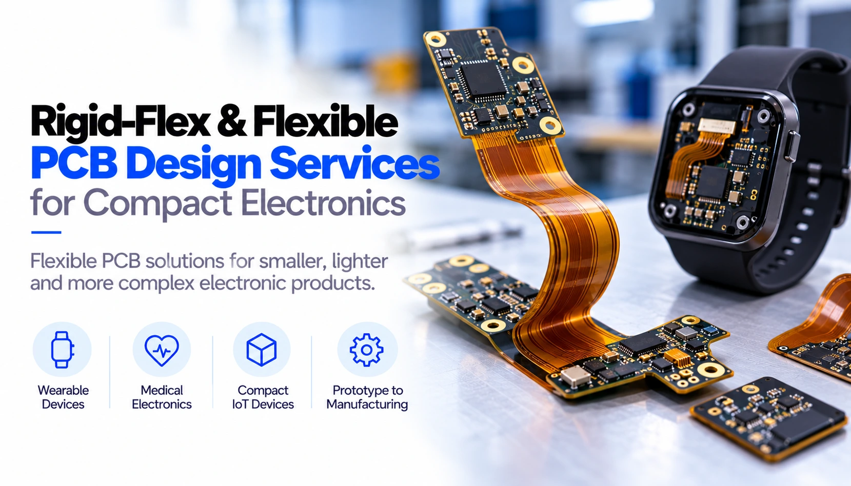
What Is the Difference Between Flex and Rigid-Flex PCBs?
Flexible PCB makes use of a flexible dielectric material which is often polyimide in place of the rigid and traditional FR-4 substrate. There can be single or multiple conductive layers present in flexible PCBs. They can also be bent in order to move through tight spaces or follow the enclosure.
Rigid-flex PCB combines rigid parts and flexible parts into one circuit. Flexible sections are usually flexible parts that interconnect two rigid components.
Rigid-flex construction can reduce the number of cables and board-to-board connectors inside a product. This may save space, simplify assembly and remove potential mechanical failure points. However, these advantages depend on careful design.
Bend geometry, copper construction, material selection and the transition between rigid and flexible regions must be planned before routing begins.
Our Rigid-Flex and Flexible PCB Design Services
Product Architecture and Mechanical Collaboration
Rigid-flex designs are based on the physical design of the product. The engineers will need to evaluate enclosure prototypes, available surface areas, heights of components, assembly orientation, and degree of movement before drafting the PCB layout.
3D PCB models and technical drawings will be used to check for bends, connections, batteries, locations of mounting surfaces, and enclosure openings. Close cooperation between the electronics and mechanics teams at the earliest stage of work can save the finished circuit from being in conflict with the enclosure design and help avoid stresses during assembly.
Flex Stack-Up and Material Selection
We develop stack-ups for single-layer, double-layer and multilayer flexible circuits, as well as combined rigid-flex assemblies.
Material choices may include polyimide substrates, flexible coverlay, suitable adhesives, stiffeners and surface finishes based on the product environment and manufacturing process. The design must also account for the fabricator's copper type, dielectric thickness, minimum feature size and registration capability.
Bend-Radius and Dynamic-Flex Planning
The required bend radius depends on the flex thickness, copper construction, number of layers and whether the circuit bends once during assembly or repeatedly during use.
We distinguish between static flex applications and dynamic flex applications. Static sections are normally folded during assembly and remain in place. Dynamic sections may experience repeated movement and require more conservative mechanical design.
Traces are routed to support the direction of bending. Sharp corners, sudden width changes, poorly located vias and copper features near high-stress regions are avoided wherever possible.
Component Placement and Flex-to-Rigid Transitions
Components, surefire holes and solderpoint connections are avoided near areas of high bending. Parts located on flexible materials may be afforded local stiffening and may require land patterns as per requirements of manufacturing.
Transition of rigid into flexible areas is given specific attention in that mechanical forces focus in that area. Making use of curved transitions, good coverlay openings and proper positioning of copper features reduce chances of cracking and delamination.
Signal, Power and RF Engineering
Compact flexible products often contain BLE, Wi-Fi, NFC, sensor and battery-management circuits. We plan reference paths, antenna clearance, power distribution and sensitive signal routing alongside mechanical constraints.
Flexible circuits may also carry USB, SPI, I²C, display or camera signals. When impedance-controlled routing is required, the geometry must be developed using the actual flex stack-up and manufacturer data.
Featured Case Study: ESP32-S3 Rigid-Flex Electronics for a Compact IoT Product
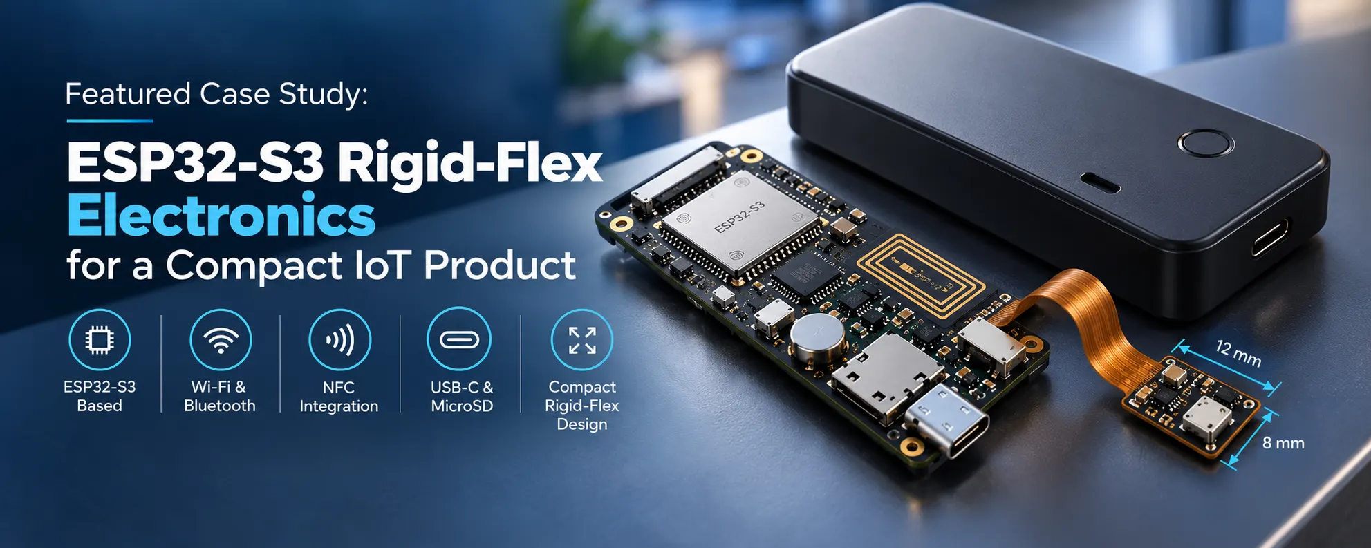
Client and Product Requirements
Adequate Infosoft cooperated with a compact IoT device manufacturer whose name is kept secret according to the project contract. The client wanted to create an electronics system that saves space and has processing capabilities, wireless communication, NFC, removable storage, USB-C connector, and a very small remote sensor unit.
All electronic devices should be placed within a compact box with dimensions of about 80 mm x 30 mm. Due to this, it would not be possible to locate every electronic component on a common rigid substrate, and using independent circuit boards will make the assembly process more difficult.
Our engineers developed two interrelated designs: a dense four-layer rigid controller PCB and a miniature two-layer flexible PCB. The rigid board handled processing, wireless communication, power and external interfaces. The flexible section positioned three components inside a restricted 12 mm × 8 mm area.
Four-Layer Rigid Controller PCB
The principal circuit board made use of the ESP32-S3 technology, it supported wireless Wi-Fi and Bluetooth connections. Besides, it included an array of options: USB-C, MicroSD, real-time clock, NFC circuitry, and FPC interconnection.
The ESP32-S3 module was placed by the edge of the circuit board made to provide the required distance for the connectivity antennas. The layout of the components and copper around the antenna was designed with a view to minimizing the risk of the housing's and the board's actions deleterious impact on wireless performance.
A custom NFC trace antenna was incorporated into the design. The NFC region was planned separately from the USB-C data paths and other noisy digital circuitry to reduce interference risks.
A four-layer structure provided dedicated reference and power regions while supporting components on both sides. The dense placement required coordination between the electrical layout and enclosure clearances rather than routing the PCB as an isolated component.
Ultra-Miniature Flexible PCB
The secondary circuit used a two-layer polyimide construction. Three components had to fit within the 12 mm × 8 mm flexible area while maintaining assembly clearances and reliable connections.
Trace corners were rounded, and the routing was aligned with the intended bend direction. The flex geometry was developed around the bend required to connect the sensor area to the main electronics through an FPC connection.
Because the circuit was extremely small, it was panelized for SMT assembly. Panelization supported component alignment and made the miniature flex circuit easier to handle during solder-paste printing, placement and reflow.
Manufacturing Preparation and Project Outcome
The project consisted of checking the three-dimensional clearance, the pin mapping, the Gerber X2 output files, the bill of materials, and the centroid files for the defined assembly process at JLCPCB.
IPC-7351 compliant component footprint files were used during the DFM stage. According to the project record, manufactured files were accepted without production delay.
This engagement demonstrates how Adequate Infosoft approaches compact electronics as a coordinated mechanical, PCB, RF and manufacturing problem. The value of the rigid-flex architecture was not flexibility alone. It enabled the electronics to occupy the available three-dimensional space while preserving wireless, interface and assembly requirements.
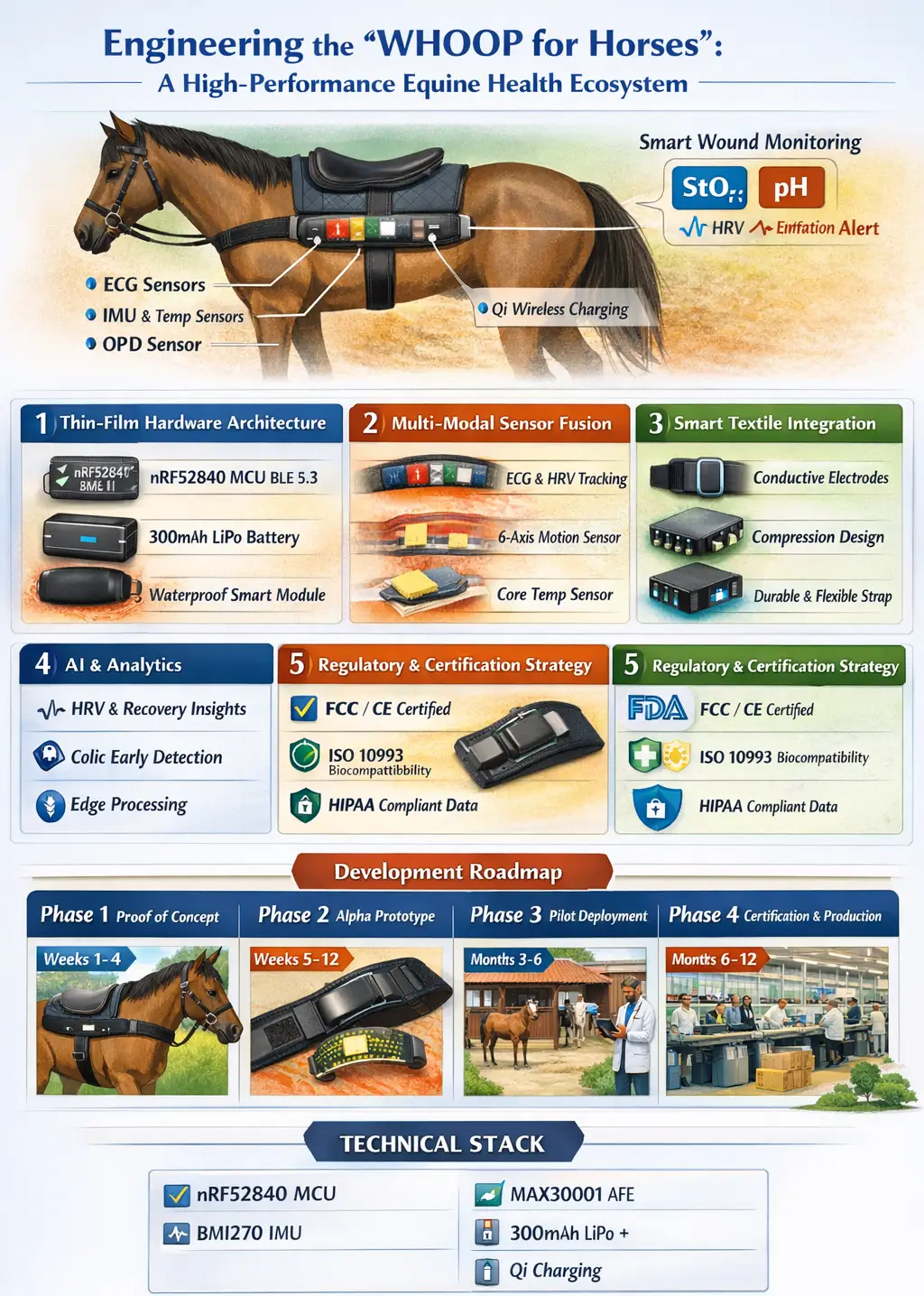
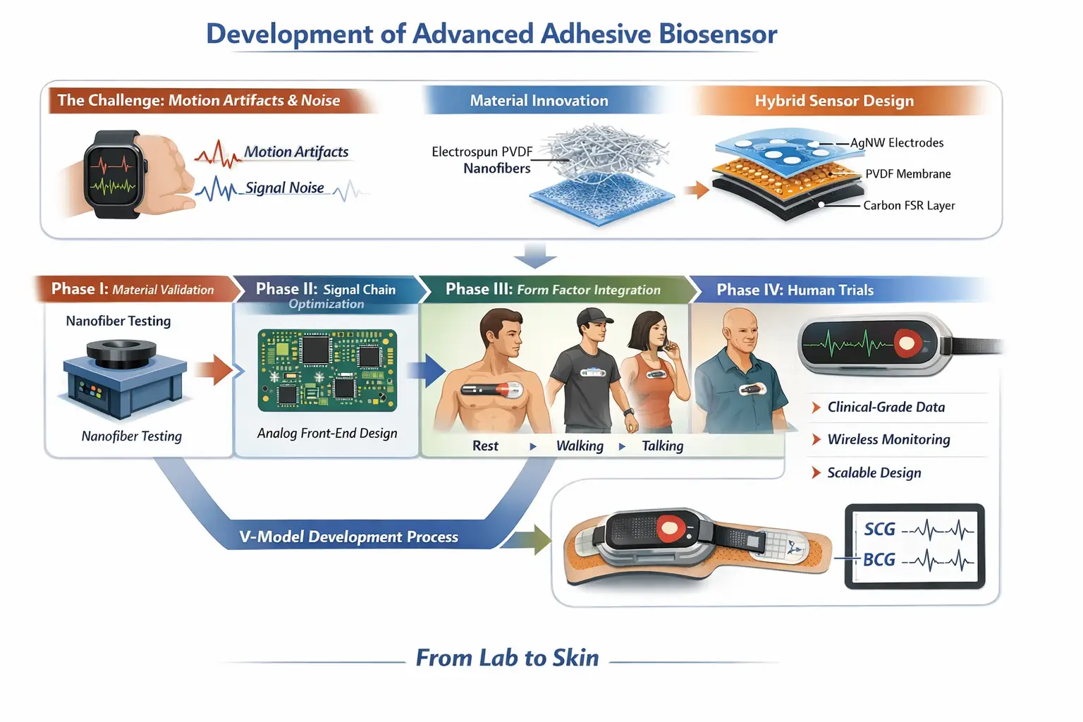
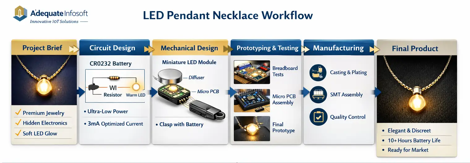
Relevant Projects That Demonstrate Our Flexible Electronics Experience
Our experience is supported by projects involving flexible circuits, conformable sensors and mechanically constrained electronic products.
Design for Manufacturing and Reliability
The design of a flexible circuit should correspond its production capabilities, which means that the examination of minimum trace widths, spacing, openings in coverlay, stiffener demands, panelization and assembly operations has to be carried out before PCB manufacturing.
The preparation for the manufacturing process may involve the following aspects:
Schematic and PCB design files Manufacturing drawings and Gerber or ODB++ files Stack-up and impedance parameters Definitions of coverlay and stiffeners Bill of materials with suppliers Pick-and-place and assembly documents 3D models and mechanical dimensions Programming and functional testing specification Prototype assembly and modification services
Also, we take the availability of components into consideration before finalizing the design. The replacement of a non-existing connector or a sensor may lead to the changes in PCB shape, stiffener and bend placement as well as the shape of the housing.
Why Choose Adequate Infosoft?
Adequate Infosoft brings together PCB designers, embedded engineers, IoT developers and application teams. This combination is valuable when the flexible circuit is only one part of a connected product.
Our expertise encompasses the design of rigid, flexible, and rigid-flex PCBs, the development of low-power electronics, the integration of both BLE and Wi-Fi technologies, design of interfaces for sensors, the process of recharging of batteries, embedded firmware solutions, mobile application creation, ensuring connectivity via clouds, and providing assistance with prototypes' manufacturing and further assembly process.
All the rights to the project deliverables and design documentation belong to clients, including all the ownership rights, source files, licenses, and production transfer obligations determined by the individual agreement.
Discuss Your Rigid-Flex PCB Project
When your product needs to bend, twist or fit into tight spaces, the engineers at Adequate Infosoft would love to hear your schematics, models, interface specifications, and estimated volumes of production.
Our engineers will help create a PCB design that allows for rigid-flex implementation, flexible circuits, wireless functionality, protoyping, and documentation.
Frequently Asked Questions
Rigid-flex PCBs are beneficial in applications where the electronics need to adapt to physical structures, function on several different levels, minimize the number of internal connection points and be able to move. They are often found in wearables, medical devices, cameras, and small IoT appliances.
Yes, but repeated movement requires a dynamic-flex design. The construction, copper type, trace direction, bend radius and expected number of cycles must be specified during development.
The bare board normally costs more. However, it may reduce connectors, cables, assembly operations and enclosure space. The correct comparison is the cost and reliability of the complete product.
It is accepted that this is possible. We have to check the schematics, the housing, the movements of the mechanical units, the heights of components, and the points of connection before we go ahead and separate them into rigid and flexible sections.
Editorial Sources