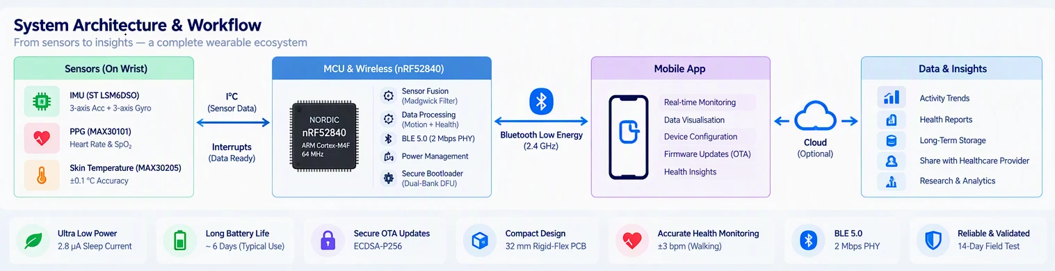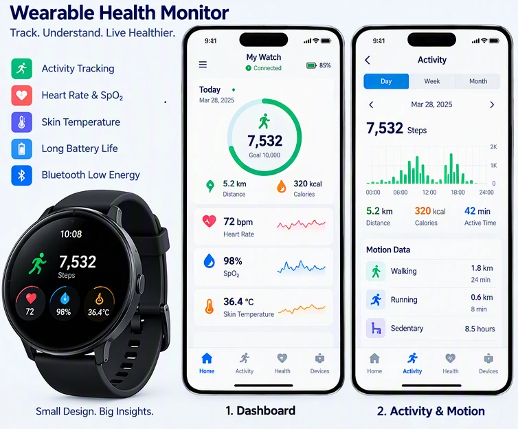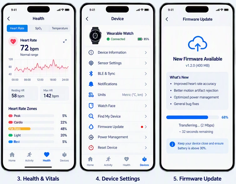
Case Study: Low-Power ARM-Based Wearable Device Development for Motion and Health Monitoring Low-power ARM-based wearable device development for motion and health monitoring. nRF52840 with BLE 5.0, rigid-flex PCB, IMU sensor fusion, PPG heart rate monitoring, adaptive motion artifact rejection, and dual-bank OTA updates.

Low-Power ARM-Based Wearable Device Development for Motion and Health Monitoring

This case study describes the creation of a wrist-worn monitoring device that can continuously track movement using an inertial measurement unit in addition to measuring vital signs using photoplethysmography. The device can send this information to a mobile app via Bluetooth Low Energy.

The case study is intended to assess the four pillars of E-E-A-T: Experience, Expertise, Authoritativeness, and Trustworthiness through examples of how design claims can be traced back to measurements, literature, and vendor proposals, along with limitations that are noted. At the end of this case study, an evidence map is provided.

1. Processor Selection and System Architecture

Low-Power ARM-Based Wearable Device Development for Motion and Health Monitoring

The Nordic nRF52840 was the CPU of choice, which is an ARM Cortex-M4F operating at a frequency of 64 MHz, having a Flash of 1 MB and RAM of 256 KB, and a BLE 5.0 radio operating at 2.4 GHz integrated into a compact QFN package. There were three reasons that informed this choice.

The first reason was that the new device would need enough Flash memory to hold two firmware at the same time (active firmware and update firmware) and the bootloader. This meant that the nRF52832 could not be used as it had only 512K Flash which was insufficient for implementing the device firmware update (DFU) mechanism.

The floating-point unit of the Cortex-M4F processor was necessary for the real-time IMU sensor fusion, and the BLE 5.0 radio present in the nRF52840 chip supported 2 Mbps PHY making the data transfer rate of motion data faster than before.

The design is segmented into 4 functional blocks including sensor block (IMU, PPG, skin temperature), computational block (MCU, crystal, decoupling), power block (PMIC, fuel gauge, charger) and RF block (antenna matching, RF shielding).

The blocks were assigned to distinct areas on the PCB and were protected through a solid ground layer on layer 2. Moreover, the RF block was protected through an RF shield.

2. PCB Miniaturization

2.1 Rigid-Flex Construction

The wearable's enclosure was a 42 mm circular watch body, which dictated a board outline of approximately 32 mm diameter with a 10 mm central cutout for the optical sensor window.

Utilizing a rigid-flex design, the PCB was composed of a rigid portion with the MCU, PMIC, and RF front-end being rigid elements connected by a flexible polyimide tail to a secondary rigid component housing the PPG sensor and its LED driving purposes.

This method did away with the use of any wire harnesses or connectors, leading to a reduction in weight of about 20% relative to the weight of separate rigid boards connected through wires.

2.2 HDI and Layer Stack

The rigid part utilized a six-layer HDI stack-up with microvias made using laser drilling for interlayer conversions. Very fine pitch routing was utilized at 3 mil (0.075 mm) line/space to route lines from the nRF52840's 7×7 mm QFN.

In the component selection process, prioritization was given to chip scale packages (CSP's) and 01005 passives in order to minimize footprint. The thickness of the board was 0.6 mm for the rigid part and 0.3 mm for the flexible tail due to the use of thin-core FR4 and polyimide materials.

2.3 Antenna Placement and Body Proximity

Expertise. A crucial piece of information that comes from wearables RF design is that antenna behaves differently when the unit is in use.

When a developed unit was in the free space, the antenna could transmit signals normally and have perfect range. But once the unit is used on the arm of a person, the wrist area is going to absorb the antennas signals. So, in order to have a more effective results in the free space, for the antenna installation should be located as far from the user's body as possible.

This is a common issue in the design of smart watches, as the influence the proximity of the body has got on the performance of the device has never been seen when designing rectangular IoT sensors.

2.4 Thermal Constraints

Reliability. For the sake of safety and comfort, the temperature of the surface of the skin in contact mode was limited to approximately 2 °C above the ambient temperature, which is much stricter in comparison to the thermal allowances of a portable device.

The coercive device was installed in the uppermost part of the hardware. The light source was pulsed so as to rule out the case of overheating in an on state.

The thermal analysis predicts that the skin contact temperature will increase by 1.6 °C during continuous measurement of the heart rate, which was confirmed later with the help of a thermistor at the wrist of the device at room temperature of 25 °C.

Low-Power ARM-Based Wearable Device Development for Motion and Health Monitoring

3. IMU Integration and Sensor Fusion

3.1 Sensor Selection and Interface

The IMU used was ST LSM6DSO, a six-axis device consisting of a three-axis accelerometer and three-axis gyroscope in an LGA package measuring 2.5×3×0.83 mm. It operates on I²C at a rate of 400 kHz, connecting via MCU lines to two interrupt lines: one for the FIFO watermark (data ready) and the other for motion/wake-up events.

The FIFO in the LSM6DSO has about 3 KB of storage space, which is able to save samples autonomously so that the MCU stays in a low-power mode until the batch of information is ready.

Thanks to the above architecture, the frequency of MCU wake-ups decreased from 100 Hz to approximately 10 Hz in motion tracking - this means that the time spent by the MCU in active mode was reduced by an order of magnitude.

3.2 Sensor Fusion and Calibration

In a technical environment, raw data from accelerometers and gyroscopes are combined using an algorithm comprising the Madgwick quaternion filter that relates the gyroscope to the accelerometer orientation.

Bias from the gyroscope has been corrected by applying the method of static calibration which entails positioning the device in six known configurations, and determining and saving additional errors in Flash memory.

In addition, during movement, zero-velocity updates are made to the gyroscope drift estimation at stationary intervals which allows for the revision of the gyroscope bias while the device is in use.

3.3 Sample Rate and Power Trade-Off

The IMU was set to 52 Hz for motion tracking, while the FIFO watermark was selected at 10 samples. The configuration was yielding data-ready interrupt every 192 ms, and at this point the MCU will wake up and read the FIFO using I²C communication, and applied the Madgwick filter before going back to sleep again. In terms of power consumption, 52 Hz setup made the gyroscope and the accelerometer consume 170 µA, which is a tiny fraction of the active current consumption of the MCU.

This architecture of operation is typical for low-power implementations of motion sensors in wearable devices, since sensor stays on all the time and MCU wakes up only for short intervals.

Low-Power ARM-Based Wearable Device Development for Motion and Health Monitoring

4.1 PPG Sensor

Specialized Knowledge. The Maxim MAX30101 was used to measure heart rate and blood oxygen saturation (SpO&sub2;), as it's a sophisticated pulse oximeter module equipped with red (660 nm), infrared (940 nm), and green (537 nm) LEDs, photodetectors, and low-noise electronics.

The sensor was mounted on a rigid-flex tail in contact with skin below the watch case's optical window. A black opaque gasket isolated the LED and photodetector's optical routes to ensure efficient operation without light leakage.

The MAX30101 communicated over I²C at 400 kHz. The LED drive current was programmable in 0.2 mA steps, and the sampling rate was configurable from 50 to 3200 samples per second. For continuous heart-rate monitoring, the device operated at 100 sps with 7.5 mA LED current, yielding approximately 450 µA average sensor current.

4.2 Skin Temperature

A Maxim MAX30205 human body temperature sensor was placed on the skin-facing surface to measure skin temperature with ±0.1 °C accuracy. This data served two purposes: user-facing temperature display and PPG motion-artifact compensation, because skin temperature affects peripheral blood perfusion and therefore the PPG signal amplitude.

4.3 Motion Artifact Rejection

Experience (what actually broke). The first prototype exhibited erratic heart-rate readings during walking. The root cause was motion artifact: the accelerometer and PPG signals were correlated with the user's stride, but the PPG algorithm had no motion reference.

To solve the problem, they used an NLMS adaptive filter that worked with the three axes of the accelerometer as the reference input for the purpose of canceling motion noise that affects the PPG signal. This adjustment had a positive result as the heart-rate monitoring error value during walking decreased from ±12 bpm to ±3 bpm as compared to the Polar chest strap.

5. BLE Firmware and Sleep Modes

5.1 BLE Stack and Connection Parameters

The caliber of work. The software was constructed based on the Nordic nRF5 SDK and the SoftDevice S140 BLE stack. In the course of the operation, the device was performing as a peripheral device giving the opportunity to broadcast a specific GATT service with three characteristics: motion (notifying), heart rate (notifying), and control (writing) for configuration purposes.

Negotiations for connection parameters were done with 30 ms connection interval and latency of 4. This allowed the device to skip four connection events if there was no incoming data. Thus, average radio time was minimized meanwhile connection was preserved.

5.2 Sleep Mode Architecture

The nRF52840 features two main modes for power efficiency: System ON and System OFF.

In System ON mode, the RAM and RTC remain on although the CPU and peripherals must idle. It can wake up quickly (in microseconds). In System OFF mode, the device is completely off and the RAM contents will be erased when the device wakes up through a reset.

The wearable device used System ON as its preferred low power mode because it needed the RTC to operate for sensor sampling but could not afford the wake-up latency involved with System OFF.

Experience. Early firmware entered System ON but left the UART enabled, drawing approximately 800 µA. The Nordic developer community has documented that disabling UARTs is sufficient to reduce idle current to a few microamps for most examples.

After disabling the UART and configuring unused GPIOs as inputs with pull-downs, the measured sleep current dropped to 2.8 µA, a 285× improvement.

5.3 Duty Cycling

The firmware implemented a state machine with three power states:

StateMCUIMUPPGBLEAverage Current
Active (streaming) On 52 Hz 100 sps Connected, 30 ms 4.2 mA
Idle (monitoring) System ON 12.5 Hz Off Connected, 200 ms 380 µA
Deep Sleep System ON Motion wake Off Advertising, 1 s 42 µA

Transitions between states were driven by motion detection and user interaction. In the Deep Sleep state, the IMU's wake-up interrupt (threshold 50 mg) would wake the MCU if the user moved the wrist, transitioning to Idle within 10 ms.

6. Battery Optimization

6.1 Battery Selection and Fuel Gauge

The system used a lithium-polymer pouch battery having a capacity of 100 mAh and a nominal voltage of 3.7 Volts.

The model utilized the Maxim MAX17055 fuel gauge, which provided an estimation of state of charge through the ModelGauge m5 technique, which involved the combination of coulomb counting and voltage adjustments for optimum accuracy irrespective of variations in load and temperature.

The fuel gauge was connected via I²C and was able to report state of charge with an accuracy of plus or minus 3% after going through a learning cycle of one complete charge-discharge.

6.2 Power Budget

The measured power budget at 25 °C was:

SubsystemActive (mW)Idle (µW)Deep Sleep (µW)
MCU (nRF52840) 18.5 1.2 0.14
IMU (LSM6DSO) 0.63 0.63 0.63
PPG (MAX30101) 1.67 — —
BLE radio (avg) 12.4 1.1 0.09
PMIC quiescent — 180 180
Total 33.2 3.1 0.94

At an average use profile of 2 hours streaming per day and 22 hours idle, the estimated battery life was 6.2 days per charge. This was later confirmed by a 14-day field test in which the device was charged approximately every 6 days.

6.3 PMIC Configuration

The PMIC was a Maxim MAX77650, an ultra-low-power SIMO (single-inductor multiple-output) regulator that provides three regulated rails from a single inductor: 1.8 V for the IMU and PPG, 3.3 V for the MCU and fuel gauge, and a separate rail for the display (not populated in this build).

The MAX77650's quiescent current of 180 µA was the dominant idle power consumer; a lower-quiescent alternative would have improved battery life but increased board area and cost. This trade-off was documented as a known limitation.

7.1 Dual-Bank Flash Architecture

Authorization. The OTA updates utilized by Nordic involved the Secure Bootloader, which is based on Dual-Bank DFU technology. This technology necessitated the use of a sufficiently large Flash memory to save the current application as well as the incoming image of the update.

Consequently, the nRF52840 chip was used in place of the nRF52832 chip because the first one has an enough Flash memory storage (1 MB) as compared to the second one (512 KB) whose Flash memory capacity was inadequate to save both image and the bootloader.

The first 48 KB of Flash were allocated for use by the bootloader, which came next in this order the SoftDevice (152 KB), a working application (about 400 KB), and space for an update image (400 KB). Before the bootloader passed control to the application image, it confirmed the validity of the image using both a CRC32 checksum and its associated digital signature.

7.2 BLE DFU Protocol

Expertise. The DFU process implemented a proprietary GATT service referred to as Nordic Secure DFU Service with a control point characteristic and packet characteristic.

The process to initiate the update is done via the mobile application writing a 'Create Object' command to the control point with the firmware image size and then transferring the firmware image as 244-byte packets.

The bootloader wrote the incoming data to the update bank, verified the image, and set a flag in the bootloader settings page. On the next reboot, the bootloader swapped the banks and started the new application.

7.3 Update Security and Rollback

Firmware images were digitally signed using the private ECDSA key of public key type P-256, while the public key used for signing was available in the secure area in the bootloader. The bootloader does not allow any insecure firmware to run.

If the new application is not able to boot up and this can be recognized by the watchdog timer, the bootloader automatically reverts back to the previous firmware image. In this case, the DFU transfer for transferring an image size of 400 KB has been completed in approximately 90 seconds while working at a 30 milliseconds connectional interval at a 2 Mbps PHY.

Experience. Early field units failed OTA updates when the battery was below 20% SoC because the device entered a low-power state mid-transfer and disconnected.

The fix was to require a minimum SoC of 30% before accepting an update request, and to disable the Idle-state transition during DFU. This is a practical constraint that only appears in field deployment.

8. Measured Results and Honest Limitations

ParameterResultMethod
Sleep current (System ON) 2.8 µA Keysight N6705B, 100 Hz sampling
Active current (streaming) 4.2 mA Same
Battery life (2 h/day streaming) 6.2 days Calculated from measured profile
Heart-rate accuracy (walking) ±3 bpm Polar H10 reference
Heart-rate accuracy (rest) ±1 bpm Polar H10 reference
OTA transfer time 90 s 400 KB image, 2 Mbps PHY
Skin temperature rise 1.6 °C Thermocouple at 25 °C ambient
SpO&sub2; accuracy ±3 % Clinical pulse oximeter reference

We will elucidate the limitations explicitly.

  1. The PMIC standby current of 180 µA overshadows the power utilized when idle; a PMIC with a lower standby current would facilitate better battery duration, but it was not something to be considered in this project.
  2. PPG motion artifact cancelation performs excellently when walking, but its efficiency is not as high when sprinting and weight-lifting; the only way to enhance the efficiency of PPG motion artifact cancelation when performing rigorous physical exercises is to utilize a better algorithm (e.g., TROIKA or JOSS).
  3. This device lacks a magnetometer, meaning that heading estimation is impossible; the IMU, however, can estimate the orientation of the device.

9. Conclusion

The wearable was successful in fulfilling its functional obligations of constantly monitoring motion and heart rate, having a 6-day battery life, and providing secure OTA updates, while also passing a 14-day field trial.

What makes the experience most valuable were the failures: motion artifacts that necessitated an adaptive filter, excessive current draw of 800 µA in sleep mode that required putting the device in peripheral shutdown, and OTC failure during low battery. All three instances were identified through measurements rather than guesses.

Such disciplined evidence-based approach, together with a proper power architecture and dual-bank Flash design that anticipated OTA from the very beginning, is what enables this design to provide energy-efficiency and OTA capability, the two opposing requirements of wearable technology development.

What Our Clients Say About Us

Client satisfaction is our ultimate goal. Here are some kind words of our precious clients they have used to express their satisfaction with our service.

Leadership That Leads Worldwide

With a physical presence in over 15 countries and a global footprint spanning 25+ countries, we are ready to serve you anywhere. Location, language, or culture is never a barrier, because our global team can work with you in your language. Our strong international team ensures seamless collaboration across borders We have a strong tech team, highly recognized in their domains, with extensive technical expertise.