


 Mean Stack Development
 Vue JS Development
 Javascript Development
 React JS Development
 Angular JS Development
 Next JS development
 Java Development
 Python Development
 Django Development
 Cherrypy Development
 C# Development
 ASP.NET Development
 NodeJS Development
 Laravel Development
 CodeIgniter Development
 Zend Development
 Ruby on Rails Development
 CakePHP Development
 PHP Website Development
 Symfony Development
 Drupal Development
 Joomla Development
 Wordpress Development
 .NET Nuke Development
 Kentico
 Umbraco
 .NET MAUI Development
 Xamarin Application Development
 iOS Application Development
 Android Application Development
 Android Wear App Development
 Ionic Development
 iBeacon Application Development
 Universal Windows Platform (UWP)
 Kotlin Application Development
 Swift Application Development
 Flutter Application Development
 PWA Application Development
 Flutter Health Tech & Wearable App Development Company
 React Native Health Tech Wearable App Development
 Offshore Software Development
 Custom Application Development
 Front-End Development
 Full Stack Development
 AI & Machine Learning
 Custom CRM Solutions
 Flask Software Development
 Electron JS Development
 ChatGPT Development
 Telemedicine App Development
 Build Smart Telemedicine Platform
 Beauty & Salon App Solutions
 Hire Workato Experts
 Magento Development
 Magento 2.0 Development
 Magento Enterprise
 Shopping Cart Development
 Prestashop Development
 Shopify Development
 Open Cart Development
 WooCommerce Development
 BigCommerce Development
 NopCommerce Development
 Virto Commerce Development
 AspDotNetStorefront Development
 .NET Application Development
 Microsoft Dynamics CRM
 VB .NET Development
 Sharepoint Migration
 ASP.NET Core Development
 ASP.NET MVC Development
 AJAX Development
 Agile Development
 Microsoft Bot
 Microsoft Blazor
 Microsoft Azure Cognitive
 HTML 5
 UI/UX Design
 Graphic Design
 Adobe Photoshop
 XML Application Development
 Cloud Computing Solutions
 Azure Cloud App Development
 AWS Development
 Google Cloud Development
 Certified AWS IoT Services Developers
 DevOps Consulting & Development
 Kubernetes Consulting & Services
 SQL Programming Development
 MySQL Development
 MongoDB Development
 Big Data
 Robotic Process Automation
 Social Media Marketing
 Search Engine Optimization
 QA Testing
 Software Testing
 Software Security
 Maintenance And Support
 I.T. Consulting Services
 Business Intelligence
 YII Development
 Data Analysis
 Alexa Skills Development
 On Demand App for Mobile repairing services
 On Demand App for Car Service Booking
 On Demand App for Cleaning Services
 On Demand App for Pharmacy
 On Demand Dedicated Developers
 On Demand Lawyer App Development











 Nuki Smart Lock
 Salto Smart Lock
 TTlock Smart Lock
 NFC App Development
 Custom IOT Enabled Smart Lock
 Smart Locker Solutions
 Hospital Smart Lock Systems
 Hotel Smart Lock Systems
 Smart Home & Office Locks
 Smart Access for Schools & Colleges
 Unloc Smart Lock Integration
 Yale & August Smart Lock Integration
 Populife Smart Lock Integration
 Smart Lock Hardware Development
 Dairy IoT Solutions
 Agri IoT & AI Solutions
 Weather & Climate Solutions
 Water & Waste Management Solutions
 RaspBerry Pi
 Firmware Software Development
 ESP 32 Software Development
 Embedded Development
 Internet of Things
 Smart IoT Development
 IoT Sensor Integration & Development Solutions
 Smart IoT System Development for HVAC
 Tuya IoT App Development
 Particle IoT SDK
 IoT Development with AI
 Smart Pet GPS Tracker
 Dairy GPS Tracking Solutions
 GPS Fleet Management Software
 Car Rental & Subscription Solutions
 Car Buy & Sell Marketplace Development
 AI-Powered Car Wash App Development
 PCB Design & Fabrication
 IoT AC Automation
 AI–IoT Painting Solutions
 IoT Wearable Hardware & App Development
 HVAC Automation & AI Control Systems
 Smart Home IoT Engineering
 AI Embedded Systems
 AI Hardware Design Service
 Advanced IoT Hardware & Firmware Development
 Device Driver Development Services
 NXP i.MX RT Firmware & Hardware Services
 Microchip PIC & AVR Development
 Hire IoT Architects
 IoT Cloud & Infrastructure Solutions
 Infineon XMC / AURIX Development Services
 Matter & Thread IoT Services
 Native IoT Mobile App Development (BLE & Wi-Fi)
 Snapdragon IoT Firmware Development
 Renesas RA/RX Firmware Services
 Silicon Labs EFR32 Development Services
 Smart Wearable App Development
 Smart IoT Meters
 Smart Healthcare Wearable App Development
 Health Care Monitoring System
 Fitness Tracking App Development
 Smart Home Automation Apps
 nRF PCB Design
 ESP32 PCB Design
 Embedded Wearables Engineers
 Rental Property Management System
 Building Management System
 Smart Lighting Development
 Infineon Semiconductor Firmware Development Services
 Custom Camera Development: Hardware, Firmware & PCB Prototyping
 Smart Security Camera SDK
 Nordic Semiconductor SDK
 Infineon SDK
 Arduino SDK
 NFC Lock Integration
 Kerong Lock Integration
 IoT & AI Solutions for Manufacturing
 Smart Inventory & Logistics Solution
 Food & Beverage Industry Solutions
 Smart Hospitality Solutions
 Smart Property Management
 Custom Smart Home IOT SDK
 Smart IoT & AI in Healthcare
 AI-Powered Security Solutions
 Smart Home Safety & AI
 Veterinary Clinic Management (AI)
 Pet Care System (AI & IoT)
 Pet Training & Adoption (AI)
 Healthcare IoT Development
 Event Management Software
 Money Remittance App
 Money Lending App Development
 Utility and Bill Payment App
 IoT Mobile App Development (Flutter & React Native)
 AI & IoT Retail Solutions
 Smart EV App Development
 Smart Solar IoT & AI Solutions
 IoT-Based Energy Systems
 Smart Energy & Utilities Solutions
 6G Solutions
 IoT Security Solutions
 AI-Powered Lottery App Development
 AI-Sports Fitness Club Management
 Travel
 Real Estate
 Medical & Healthcare
 e-Learning
 Consumer Products
 Finance
 Automobile
 Media & Entertainment
 Billing Software
 Enterprise Resource Planning (ERP)
 Augumented & Virtual Reality
 Point of Sale(POS) Development
 Learning Management System
 EV Charging Solutions
 About Us
 Partners & Certifications
 Quality Assurance
 Our Clients & Testimonials
 Development Process
 Our Products
 Social Responsibility
 Work Ethics
 Vision & Mission
 Awards
 Live Project Demos
 Contact Us
 Case Studies
 Portfolio
 Blog
PCB Assembly & Prototype Manufacturing Support Services
A PCB design becomes a product only after real boards have been fabricated, assembled, programmed and tested.
This transition is where many promising hardware projects slow down. A footprint does not match the purchased component.
An assembly house cannot source a specified part. The first board powers up but cannot be programmed.
A wireless device works on the bench yet loses range inside its enclosure. Ten prototypes operate correctly, but the pilot batch produces inconsistent results.
Adequate Infosoft provides PCB assembly and prototype manufacturing support for startups, product companies, OEMs and industrial engineering teams. We coordinate the technical path from approved PCB files to assembled, functioning and documented hardware.
The service we provide is design-for-manufacturing review, contact with suppliers, sourcing components, manufacturing products, assembling SMT, flashing firmware, testing boards, and doing pilot-production readiness work.
We work in the area of wireless IoT devices, medical wearables, cameras, robotics, industrial controllers, power electronics and consumer products.
Let's Work Together!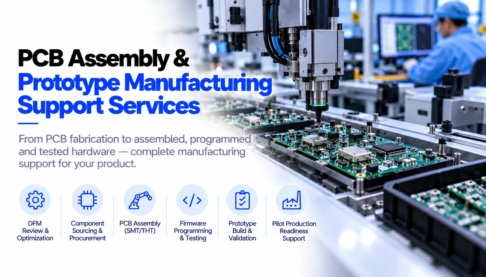
Prototype Manufacturing Is an Engineering Phase
The prototype assembly is perceived as purchasing process: you just upload Gerber files, procure the components and wait for boards. In fact, it is an engineering process.
The manufacturer may have doubts as to the stack up or the controlled impedance design.
The assembler may need to use a different packaging or a different panelizing method. A different component may change the electrical performance.
It is our task to make sure that PCB designer, embedded developer, component supplier, manufacturer and assembler all are working with the same technical information.
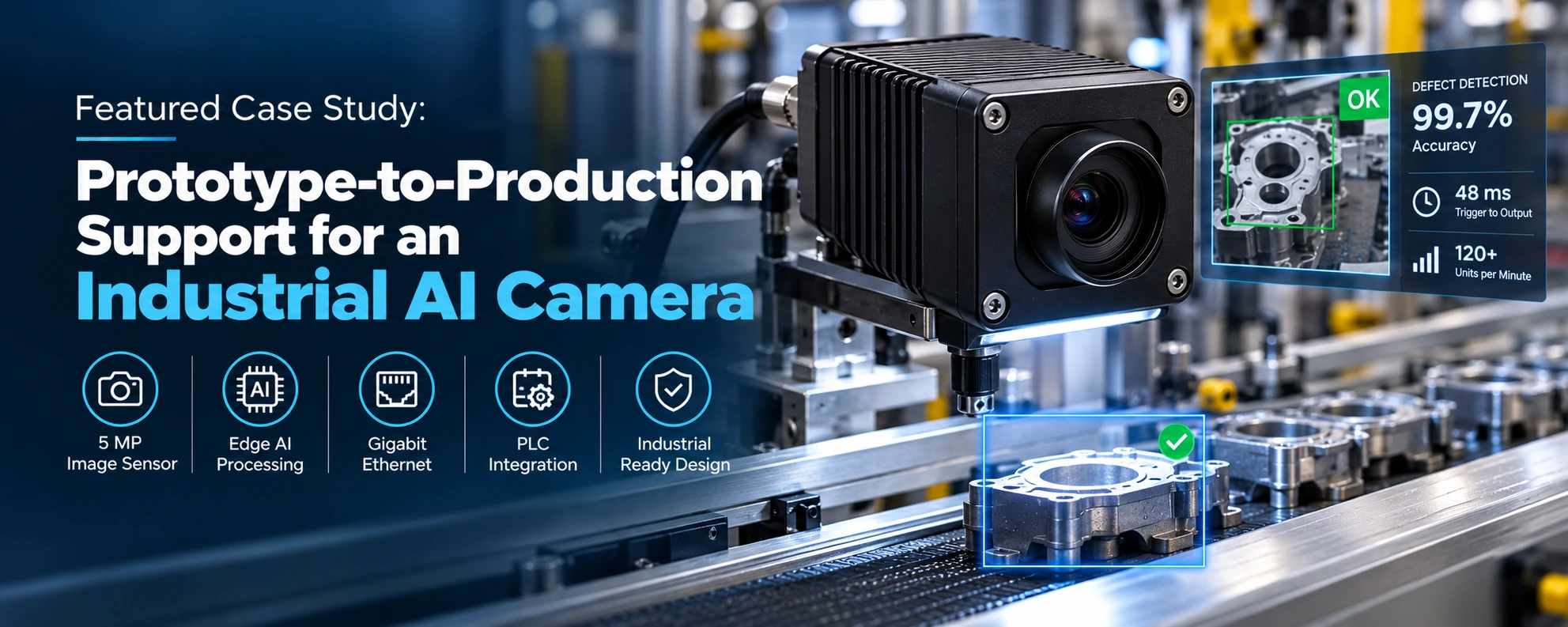
Featured Case Study: Prototype-to-Production Support for an Industrial AI Camera
The Client and Production Requirement
A startup in the field of industrial automation from North America has chosen Adequate Infosoft for the development of a small-sized smart camera for the examination of goods moving in factories.
The requirement of the camera was to capture images in the resolution of 5 MP, conduct defect detection through edges, communicate with factory PLC machines, and work in an uninterrupted manner in a dusty industrial setting.
The product could not remain a collection of development boards. It required custom hardware, tested firmware, an enclosure, manufacturing files and assembled units suitable for installation at operating factories.
Custom PCB and Prototype Build
An eight-layer PCB measuring 90 mm × 70 mm was created by our team, which contains an NXP i.MX RT1060 processor, AR0521 image sensor, DDR3 memory, eMMC storage, Edge TPU accelerator, Gigabit Ethernet, optically isolated I/O, and a high-current LED driver.
For the MIPI camera interface, routing of controlled impedance was necessary. The DDR signals called for topology and length design while an adequate thermal path to the enclosure was necessary for the Edge TPU.
The first manufacturing stage used two hand-assembled custom PCB prototypes. Board bring-up confirmed the power rails and major interfaces, but MIPI performance required further layout optimisation. The affected routes were revised with improved matching and shielding.
Thermal testing also showed that the accelerator required a more direct heat-transfer path. A thermal pad, via array and enclosure contact were incorporated before the design moved forward.
From Engineering Samples to a Pre-production Batch
After the revised board completed bring-up, Adequate Infosoft coordinated a 25-unit pre-production run via an assembly plant.
The manufacturing package contained Altium schematics, PCB source, Gerber files, BOM, pick-and-place data, and assembly documents. Correspondingly, the firmware package, hardware testing procedures and enclosure drawings were matched with the version of the board released.
All 25 units completed the documented factory acceptance process. Testing covered camera operation, AI inference, PLC communication, temperature, vibration, power and network behaviour.
The reported results included an average trigger-to-output latency of 48 ms, operation above the 120-unit-per-minute target and industrial EMC and vibration test completion.
Deployment and Production Learning
Two cameras were first installed on one production line. This pilot stage exposed real lighting, surface-reflection and operating-condition issues that were difficult to reproduce completely on a bench.
After field adjustment, 25 cameras were deployed across three plants for continuous operation. The project's published records report 99.7% defect-detection accuracy and 99.5% operational availability, excluding planned maintenance.
The case demonstrates why prototype manufacturing should be treated as controlled product development. Design revision, assembly data, firmware, thermal management, factory tests and field validation were managed as one connected process rather than separate handovers.
Case Study URL: ai-based-camera-development-nxp-imx-firmware-pcb-design
Relevant Delivered Projects That Build Buyer Confidence
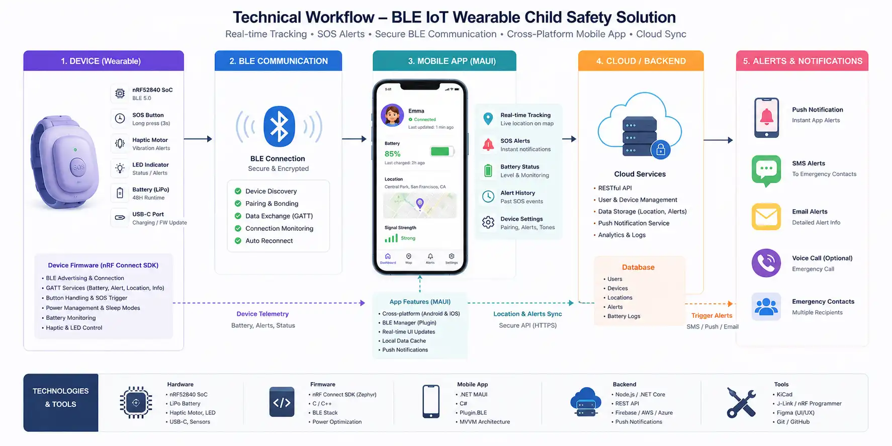
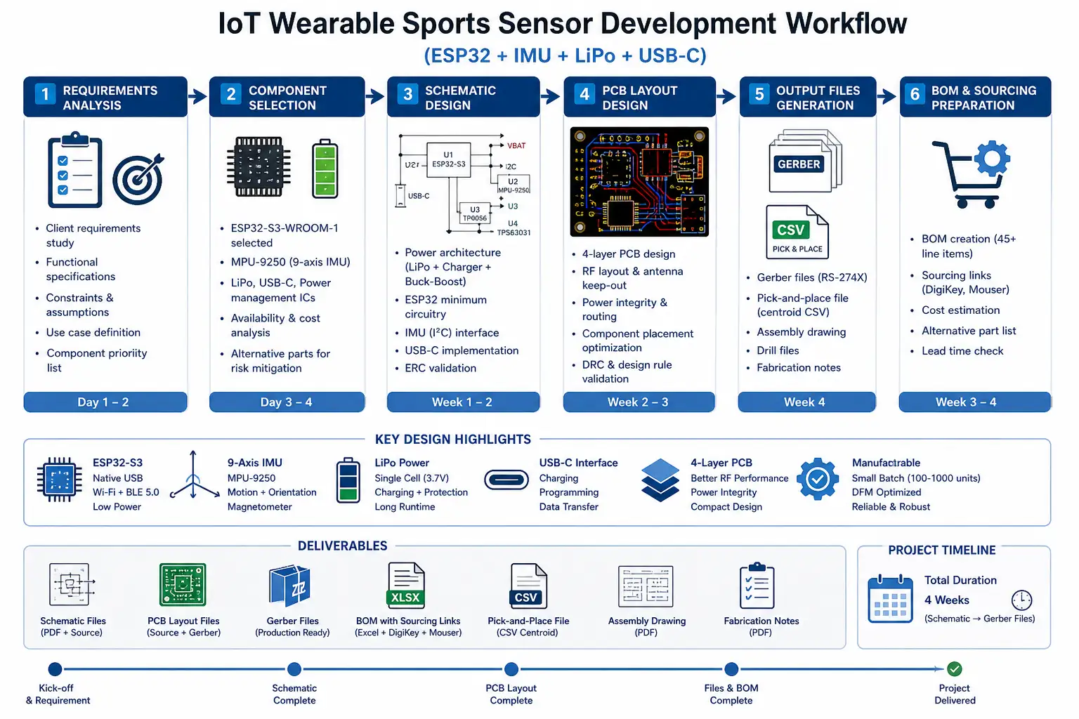
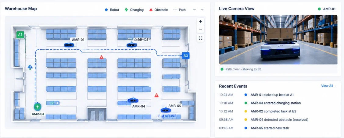
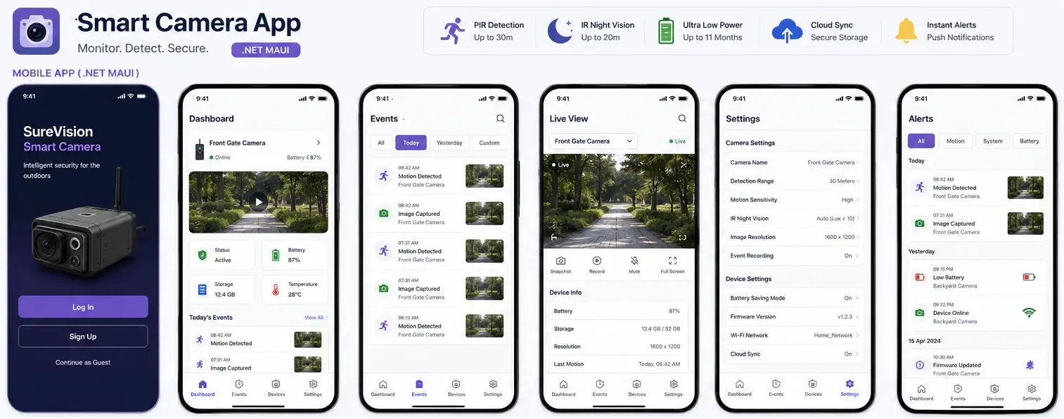
A Gate-Based Path from PCB Files to Working Hardware
Gate 1: Manufacturing-File Examination
Prior to issuing an order, we complete a fabrication and assembly package verification. The package can consist of original design files, Gerber or ODB++ outputs, NC drill files, board outline, stack-up, impedance requirements, BOM, pick-and-place data, assembly drawings and 3D models.
We make sure that there is revision consistency – the schematic, PCB, BOM, and assembly information provide the same design information of circuit board.
Gate 2: DFM and Component Readiness
The design is compared to the capacities of the chosen manufacturer. The examination includes rules of trace and spacing, perforation sizes, annular rings, solder mask openings, clearance, surface finish, panelization, and placement of the component.
The bills of materials go through evaluation of lifecycle status, stock availability, lead time, and packaging. Changes in components are introduced only after consideration of its electrical, mechanical, and firmware impact has been carried out.
Gate 3: Manufacturing and Assembly Collaboration
Assistance is provided in the area of rigid, flexible, rigid-flex and multilayer PCB prototypes. The task of assembly can involve various methods of SMT, through-hole or other combinations.
At the beginning stage of production, it is important to note component orientation, reference designator, centroid and polarity. For certain designs, adjustments in stencil printing are needed, in addition to controlled heating and using X-ray inspection.
Gate 4: Controlled Board Bring-Up
A newly assembled board should not be connected to full power without a plan.
Bring-up normally begins with visual inspection, resistance checks and current-limited power. Rails, reset, clocks and boot configuration are verified before firmware is loaded. Interfaces and subsystems are then enabled in a controlled sequence.
Gate 5: Pilot-Production Evidence
A working engineering sample differs from that of a production-ready item. Pilot productions are necessary in order to assess programming efficiency, the incidence of assembly faults, reworking, calibration times, and the outcomes of functional testing.
The results obtained will help the engineers perfect the production output before making the decision about a large run of goods.
What Professional PCB Buyers Need Confirmed
Controlled-Impedance Routing and Stack-Up
Impedance targets must be based on the actual material and stack-up offered by the PCB fabricator. We communicate the required structures and review supplier feedback before fabrication.
Antenna Clearance and Matching for Wireless Prototypes
Prior to final production, various aspects, such as antenna clearance, feed geometry and matching requirements are considered. Furthermore, RF testing will be completed with the enclosure, power sources and cables used.
Signal and Power Integrity
Prototype validation includes checking power rails during startup, sleep, transmission and peak processing loads. High-speed interfaces are exercised under realistic traffic rather than tested only for basic connectivity.
EMI and EMC Risk
Layout, switching converters, clocks, connectors and cables are reviewed for emission and immunity risks. Pre-compliance testing can identify problems before formal certification.
Thermal Management
Charging devices, regulators, processors, LEDs, and power components undergo evaluation under constant load. Hot spots not captured in brief laboratory measurements can be traced with thermal imaging and stress testing.
Component Availability
Long lead, obsolete and sole-source components are discovered before the prototype order is placed. Approved alternatives are recorded and not just mentioned informally by the company doing the assembly work.
DFM, DFT and Test-Point Accessibility
DFM helps the board match fabrication and assembly processes. DFT provides access for power verification, programming, calibration and diagnosis.
Test points must be reachable by probes or fixtures while avoiding unnecessary stubs on high-speed or RF paths.
Factory Programming
A repeatable programming process should specify the connector or fixture, firmware version, boot configuration, serial-number assignment, security-key provisioning and verification result.
Measurement of Production Yield
Yield is observed for each batch. Recording the manufacturing defects, mounting errors, soldering errors, programming errors, calibration errors and rework is suggested.
Total Ownership of Design File
The parties should conclude on the ownership before starting production. The customer should be aware of which original PCB files, libraries, production outputs, firmware, fixtures and testing documentation will be transferred.
Delivery of Prototype and Manufacturing Material
Based on the requirement, we can deliver:
Compilation of fabrication and assembly files Approved BOM with alternatives equipped for supplier Various sorting methods including Gerber and ODB++ Illustration of pick-and-place and assembly Options for panelization Support in prototype assembly Package of firmware programming Board startup checklist Set of procedures for operating and calibrating History of failures and rework Pilot manufacturing yield report Paperwork for production phase
Move from Design Files to Tested Hardware
Building a working prototype involves much more than simply purchasing a bare PCB. It requires proper files, components, an assembly process, safe power-up, firmware and test results.
Please send your files, bill of materials, desired number of pcs, enclosures and test needs to Adequate Infosoft. We will plan the quickest and most responsible route from PCB data to assembled hardware.
Frequently Asked Questions
Yes. Initially we check all available documentation of the design and production files. Any possible risks or data shortages are outlined before the assembly process is initiated.
The number depends on test coverage, destructive testing, certification samples and investor or field-trial needs. Small engineering runs often begin with a few units, followed by a larger pilot batch after validation.
We support fabrication and assembly through qualified manufacturing partners while managing the engineering documentation, supplier questions, bring-up and test process.
Yes. We can assist with the modifications in the design, searching for necessary components, assembling the circuit with the aid of special instruments, conducting pilot production, analysis of the product if any defects occur, and providing all information to the chosen contract manufacturer.
Editorial Sources