














 Mean Stack Development
 Vue JS Development
 Javascript Development
 React JS Development
 Angular JS Development
 Next JS development
 Java Development
 Python Development
 Django Development
 Cherrypy Development
 C# Development
 ASP.NET Development
 NodeJS Development
 Laravel Development
 CodeIgniter Development
 Zend Development
 Ruby on Rails Development
 CakePHP Development
 PHP Website Development
 Symfony Development
 Drupal Development
 Joomla Development
 Wordpress Development
 .NET Nuke Development
 Kentico
 Umbraco
 .NET MAUI Development
 Xamarin Application Development
 iOS Application Development
 Android Application Development
 Android Wear App Development
 Ionic Development
 iBeacon Application Development
 Universal Windows Platform (UWP)
 Kotlin Application Development
 Swift Application Development
 Flutter Application Development
 PWA Application Development
 Flutter Health Tech & Wearable App Development Company
 React Native Health Tech Wearable App Development
 Offshore Software Development
 Custom Application Development
 Front-End Development
 Full Stack Development
 AI & Machine Learning
 Custom CRM Solutions
 Flask Software Development
 Electron JS Development
 ChatGPT Development
 Telemedicine App Development
 Build Smart Telemedicine Platform
 Beauty & Salon App Solutions
 Hire Workato Experts
 Magento Development
 Magento 2.0 Development
 Magento Enterprise
 Shopping Cart Development
 Prestashop Development
 Shopify Development
 Open Cart Development
 WooCommerce Development
 BigCommerce Development
 NopCommerce Development
 Virto Commerce Development
 AspDotNetStorefront Development
 .NET Application Development
 Microsoft Dynamics CRM
 VB .NET Development
 Sharepoint Migration
 ASP.NET Core Development
 ASP.NET MVC Development
 AJAX Development
 Agile Development
 Microsoft Bot
 Microsoft Blazor
 Microsoft Azure Cognitive
 HTML 5
 UI/UX Design
 Graphic Design
 Adobe Photoshop
 XML Application Development
 Cloud Computing Solutions
 Azure Cloud App Development
 AWS Development
 Google Cloud Development
 Certified AWS IoT Services Developers
 DevOps Consulting & Development
 Kubernetes Consulting & Services
 SQL Programming Development
 MySQL Development
 MongoDB Development
 Big Data
 Robotic Process Automation
 Social Media Marketing
 Search Engine Optimization
 QA Testing
 Software Testing
 Software Security
 Maintenance And Support
 I.T. Consulting Services
 Business Intelligence
 YII Development
 Data Analysis
 Alexa Skills Development
 On Demand App for Mobile repairing services
 On Demand App for Car Service Booking
 On Demand App for Cleaning Services
 On Demand App for Pharmacy
 On Demand Dedicated Developers
 On Demand Lawyer App Development






 Nuki Smart Lock
 Salto Smart Lock
 TTlock Smart Lock
 NFC App Development
 Custom IOT Enabled Smart Lock
 Smart Locker Solutions
 Hospital Smart Lock Systems
 Hotel Smart Lock Systems
 Smart Home & Office Locks
 Smart Access for Schools & Colleges
 Unloc Smart Lock Integration
 Yale & August Smart Lock Integration
 Populife Smart Lock Integration
 Smart Lock Hardware Development
 Dairy IoT Solutions
 Agri IoT & AI Solutions
 Weather & Climate Solutions
 Water & Waste Management Solutions
 RaspBerry Pi
 Firmware Software Development
 ESP 32 Software Development
 Embedded Development
 Internet of Things
 Smart IoT Development
 IoT Sensor Integration & Development Solutions
 Smart IoT System Development for HVAC
 Tuya IoT App Development
 Particle IoT SDK
 IoT Development with AI
 Smart Pet GPS Tracker
 Dairy GPS Tracking Solutions
 GPS Fleet Management Software
 Car Rental & Subscription Solutions
 Car Buy & Sell Marketplace Development
 AI-Powered Car Wash App Development
 PCB Design & Fabrication
 IoT AC Automation
 AI–IoT Painting Solutions
 IoT Wearable Hardware & App Development
 HVAC Automation & AI Control Systems
 Smart Home IoT Engineering
 AI Embedded Systems
 AI Hardware Design Service
 Advanced IoT Hardware & Firmware Development
 Device Driver Development Services
 NXP i.MX RT Firmware & Hardware Services
 Microchip PIC & AVR Development
 Hire IoT Architects
 IoT Cloud & Infrastructure Solutions
 Infineon XMC / AURIX Development Services
 Matter & Thread IoT Services
 Native IoT Mobile App Development (BLE & Wi-Fi)
 Snapdragon IoT Firmware Development
 Renesas RA/RX Firmware Services
 Silicon Labs EFR32 Development Services
 Smart Wearable App Development
 Smart IoT Meters
 Smart Healthcare Wearable App Development
 Health Care Monitoring System
 Fitness Tracking App Development
 Smart Home Automation Apps
 nRF PCB Design
 ESP32 PCB Design
 Embedded Wearables Engineers
 Rental Property Management System
 Building Management System
 Smart Lighting Development
 Infineon Semiconductor Firmware Development Services
 Custom Camera Development: Hardware, Firmware & PCB Prototyping
 Smart Security Camera SDK
 Nordic Semiconductor SDK
 Infineon SDK
 Arduino SDK
 NFC Lock Integration
 Kerong Lock Integration
 IoT & AI Solutions for Manufacturing
 Smart Inventory & Logistics Solution
 Food & Beverage Industry Solutions
 Smart Hospitality Solutions
 Smart Property Management
 Custom Smart Home IOT SDK
 Smart IoT & AI in Healthcare
 AI-Powered Security Solutions
 Smart Home Safety & AI
 Veterinary Clinic Management (AI)
 Pet Care System (AI & IoT)
 Pet Training & Adoption (AI)
 Healthcare IoT Development
 Event Management Software
 Money Remittance App
 Money Lending App Development
 Utility and Bill Payment App
 IoT Mobile App Development (Flutter & React Native)
 AI & IoT Retail Solutions
 Smart EV App Development
 Smart Solar IoT & AI Solutions
 IoT-Based Energy Systems
 Smart Energy & Utilities Solutions
 6G Solutions
 IoT Security Solutions
 AI-Powered Lottery App Development
 AI-Sports Fitness Club Management
 Travel
 Real Estate
 Medical & Healthcare
 e-Learning
 Consumer Products
 Finance
 Automobile
 Media & Entertainment
 Billing Software
 Enterprise Resource Planning (ERP)
 Augumented & Virtual Reality
 Point of Sale(POS) Development
 Learning Management System
 EV Charging Solutions
 About Us
 Partners & Certifications
 Quality Assurance
 Our Clients & Testimonials
 Development Process
 Our Products
 Social Responsibility
 Work Ethics
 Vision & Mission
 Awards
 Live Project Demos
 Contact Us
 Case Studies
 Portfolio
 Blog
Blog
STM32G4 Motor Control, FOC & Digital Power Firmware Development
Adequate Infosoft provides STM32G4 motor control development for products where current measurement, PWM timing, protection, and control-loop execution must work as one deterministic system.
Our engineers develop field-oriented control (FOC), BLDC/PMSM drives, electronic speed controllers, servo and pump controllers, digital power converters, custom PCBs, communications, test software, and production firmware.
The products, algorithm migration, unstable prototypes, performance optimization, and transfer to production are supported by us.
The project can start from the specification, the evaluation kit, the schematics, and firmware database or from the bench unit not meeting efficiency, noise, transient response, thermal properties, or EMC criteria.
Let's Work Together!
Why STM32G4 Is Built for Real-Time Control
The STM32G4 family consists of a 170 MHz processor - ARM Cortex M4 with hardware facilities for floating-point, DSP, mixed-signal I/O, fine-timers, and systems for mathematical calculations.
The chosen components allow 12 bit ADCs with hardware oversampling, operational amplifiers, comparators, DACs, motor control timers, high-resolution timers.
STM32G474 offers CORDIC and FMAC accelerators, five ADCs with 4 Msps speed, six op-amps, seven comparative components, and three motor control timers. These components help lower the CPU load and outside electronic components of the system.
That integration does not make every STM32G4 interchangeable. Pin count, flash and RAM, ADC allocation, HRTIM availability, temperature grade, communications, and simultaneous peripheral use determine the correct ordering code. We create a resource map before freezing the MCU or PCB.
Two Control Domains, One Engineering Discipline
Motor drives and switched-mode supplies serve different loads, but both must measure a noisy system, execute control law by a fixed deadline, update switches precisely, and reach a safe state before a fault causes damage.
| Engineering domain | Typical algorithms and functions | Representative products |
|---|---|---|
| Motor control | FOC, Clarke/Park transforms, PI current loops, SVPWM, observers, speed and position loops | Pumps, fans, compressors, robotics, drones, tools, appliances |
| Digital power | Voltage/current-mode control, digital compensation, phase and frequency control, soft start, current sharing | Buck/boost, PFC, LLC, battery chargers, inverters, LED and industrial supplies |
Relevant Case Studies Proving Our Expertise
The following published projects demonstrate relevant delivery experience. Where another MCU was used, we identify it openly and apply only the transferable engineering evidence.
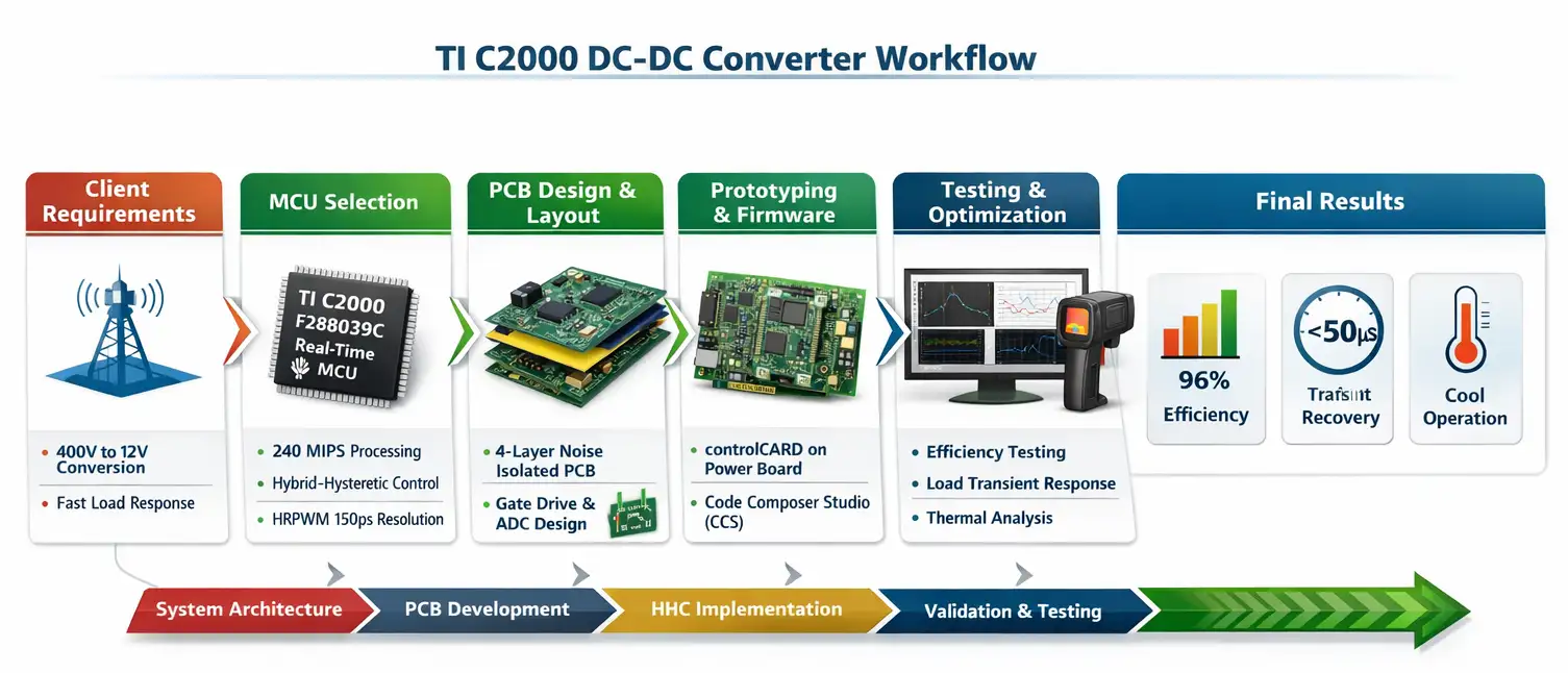
1 kW resonant DC-DC converter using TI C2000
Adequate Infosoft came up with a prototype of a resonant converter that can convert 400 V to 12 V using TI's F280039C real-time MCU.
The publication discusses details related to custom PCB design, high-resolution PWM, synchronized sensing, control, noise mitigation and control, transient tuning, and thermal validation.
Although not STM32G4, it demonstrates transferable digital-power engineering.
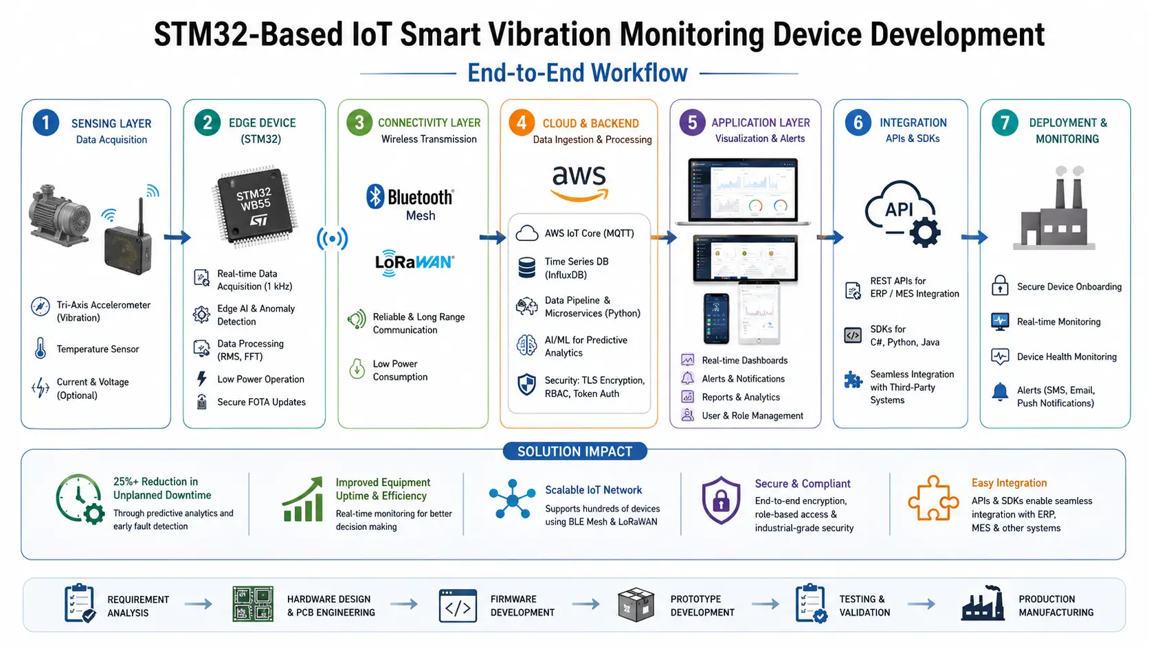
STM32 vibration monitoring for rotating machinery
This STM32 industrial device acquires vibration data for predictive maintenance. Its sampling, filtering, embedded processing, communications, and field observability help correlate controller behavior with mechanical condition.
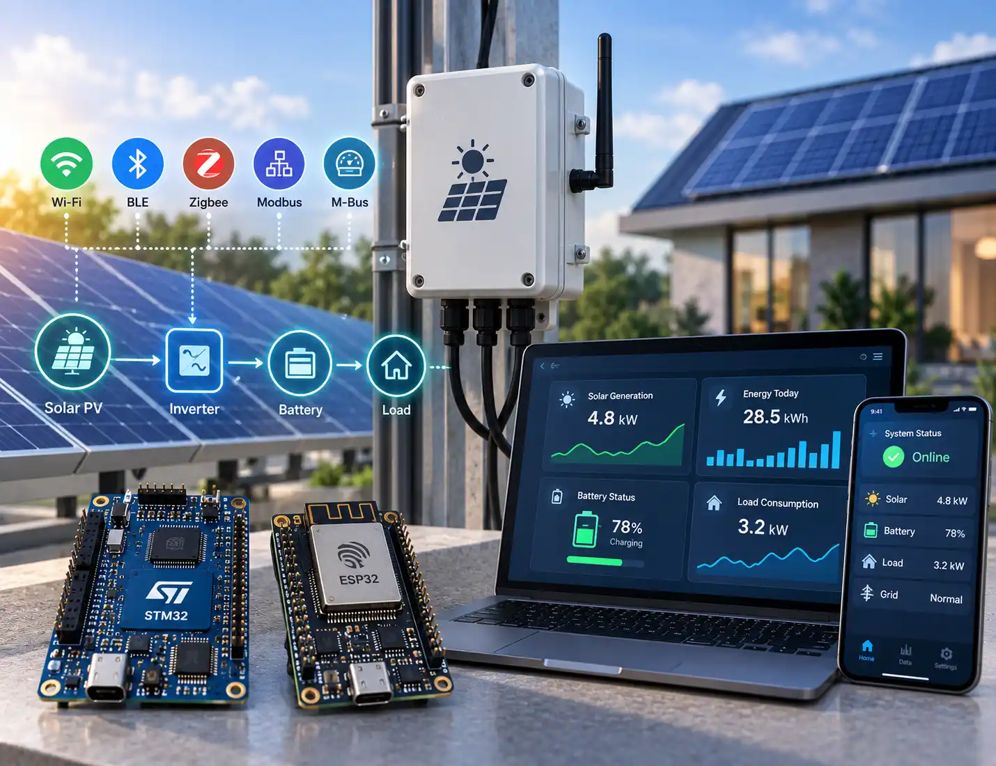
STM32 solar-energy monitoring and control
The Sunsystem project makes use of firmware written for STM32 and ESP32 for electrical monitoring, Zigbee, BLE, Wi-Fi, Modbus and M-Bus for communication.
STM32G4 FOC and Motor-Control Services
Motor and power-stage characterization
Control works on the principles of the motor plus inverter. We define such terms as bus range, phase current, pole pairs, resistance, inductance, flux linkage, inertia, load, speed, switching frequency, and boundaries for temperature.
The ST Motor Profiler and MCSDK make the identification of PMSM faster; however, the test data must also be analyzed at the workbench and tested at all necessary temperatures.
Sensored and sensorless FOC
We deploy d/q current loops, torque, speed or position loops, coordinate transformations, space vector pulse width modulation, current reconstruction, motor alignment, braking, and transition between state.
Sensors used for feedback might include Hall devices, encoders, resolver interfaced externally, or observer based on sensorless technology.
Sensorless control is application-specific. Startup load, low-speed observability, acceleration, field weakening, and regeneration change the design. We evaluate applicable MCSDK observer options, including STO/PLL and CORDIC-based processing, then validate the complete speed-torque envelope.
Current sensing and analog integration
We develop one-, two-, three-shunt, or isolated current-sensing architectures, including gain, calibration, ADC triggers, blanking, reconstruction, filtering, and overcurrent thresholds.
Integrated op-amps and comparators may reduce BOM and latency, external devices remain preferable where isolation, accuracy, or safety requires them.
Startup, efficiency, and acoustic refinement
When it comes to our tuning process, we adjust variables such as ramps, dead times, modulation, flux weakening, and maximum torque per amp depending on the case. We also consider feed-forward terms and loop bandwidth.
We conduct testing such as stall, reversal, load steps, bus variation, temperature, low-speed cogging, vibration, audible tones, braking energy, and starting repeatedly.
For related end-to-end capabilities, see our BLDC motor controller PCB and firmware development services.
STM32G4 Digital Power Development
Converter topology and control-loop design
We provide assistance for buck circuits, boost circuits, buck-boost circuits, flyback circuits, phase-shifted circuits, and resonant circuits, PFC levels, regulating units, LED drivers, and supply components. Coverage is determined by power, switch technology, isolation, voltage, safety, and efficiency.
Firmware can cover PWM, synchronized ADC sampling, digital compensation, current and voltage loops, feed-forward, soft start, burst modes, synchronous rectification, current sharing, pre-charge, discharge, and state sequencing. Compensation is derived, then confirmed through frequency-response or transient measurements.
High-resolution timing and fast protection
HRTIM's controller allows the STM32G4 to develop sophisticated waveforms with very tight control suitable for high-frequency conversion. The functionality of complementary output generation, dead time, phase shift, repetition frequency, burst mode, ADC trigger signaling, and fault inputs are specified here.
Break paths are enabled and disable the switching in case of a fault occurrence, without waiting for the software task.
The B-G474E-DPOW1 Discovery kit is a useful starting point, with an onboard buck-boost converter, USB Power Delivery, and power-conversion examples. A kit may prove an algorithm; custom magnetics, gate drive, isolation, creepage, thermal design, and PCB parasitics still determine product performance.
Firmware Architecture, Diagnostics, and Connectivity
In the synchronized interrupt paths, time-critical control operates independently from the type of operations performed in slower state machines, like communications, logging, and user interface.
We do a cost estimation according to the worst case execution time of each task, prioritize interrupts, place critical code and data in appropriate locations and instrument deadlines. CORDIC and FMAC are used where profiling indicates advantage.
Product firmware may include CAN FD, UART, SPI, I2C, USB, Modbus, diagnostics, calibration storage, a bootloader, updates, event history, and manufacturing mode. Telemetry cannot starve the control loop. Fault snapshots preserve key measurements and controller state around a trip.
Custom Inverter and Power-Control PCB Design
Adequate Infosoft can deliver a control board or complete electronics: schematic, gate drivers, power switches, sensing, isolation, supplies, encoder interfaces, protection, communications, multilayer PCB, BOM, prototypes, and production-test points.
Layout is part of control performance. We minimize switching loops, define gate returns, apply Kelvin sensing, separate power and measurement paths, control common-mode currents, and manage heat. High-voltage designs also require appropriate creepage, clearance, insulation, discharge behavior, and safety review. Learn more about our STM32 PCB design and prototyping services.
Protection Is a System, Not a Single Threshold
We combine hardware-fast protection with firmware supervision: cycle-by-cycle overcurrent, short circuit, gate-driver fault, shoot-through prevention, bus under/overvoltage, overtemperature, overspeed, stall, phase loss, sensor plausibility, watchdog, brownout, communications timeout, and safe restart.
A trip must produce a defined outcome. Tests verify how outputs are disabled, whether energy can regenerate into the bus, what remains latched, which evidence is stored, and what authorization or cooldown is required before restart. Safety-related products may require independent protection, formal hazard analysis, traceability, and standards-specific development beyond standard firmware testing.
Verification from Model to Loaded Hardware
Verification progresses through simulation, unit tests, processor- or hardware-in-the-loop tests, low-voltage bring-up, dynamometer or electronic-load testing, and operation across the specified envelope.
Evidence may include loop bandwidth, speed regulation, torque ripple, efficiency, startup success, position accuracy, transient response, output ripple, protection time, EMC pre-scan, thermal rise, CPU headroom, and endurance. Conditions, firmware, PCB revision, calibration, and instruments are recorded for reproducibility.
Frequently Asked Questions
Definitely yes. STM32G4 is part of ST's motor control ecosystem supporting PMSM/BLDC FOC and the sensorless observer options.
Whether the component is appropriate for a specific application depends on factors such as the starting load, minimum speed of operation, motor characteristics, sensing, inverter design, and dynamics.
Selected STM32G4 devices and MCSDK configurations support dual-motor designs, but ADC, timer, DMA, CPU, memory, and pin allocation must be proven for the required PWM and loop rates. Separate safety paths may also be necessary.
Definitely yes. ST has the capability to analyze the MCSDK-based firmware or any other firmware made by the customer, replicate the bugs discovered in the firmware, investigate the timing, optimize sensing/control, add the communication/protection features, perform the migration between the STM32 devices, and create the regression testing before the release.
Editorial Sources