













 Mean Stack Development
 Vue JS Development
 Javascript Development
 React JS Development
 Angular JS Development
 Next JS development
 Java Development
 Python Development
 Django Development
 Cherrypy Development
 C# Development
 ASP.NET Development
 NodeJS Development
 Laravel Development
 CodeIgniter Development
 Zend Development
 Ruby on Rails Development
 CakePHP Development
 PHP Website Development
 Symfony Development
 Drupal Development
 Joomla Development
 Wordpress Development
 .NET Nuke Development
 Kentico
 Umbraco
 .NET MAUI Development
 Xamarin Application Development
 iOS Application Development
 Android Application Development
 Android Wear App Development
 Ionic Development
 iBeacon Application Development
 Universal Windows Platform (UWP)
 Kotlin Application Development
 Swift Application Development
 Flutter Application Development
 PWA Application Development
 Flutter Health Tech & Wearable App Development Company
 React Native Health Tech Wearable App Development
 Offshore Software Development
 Custom Application Development
 Front-End Development
 Full Stack Development
 AI & Machine Learning
 Custom CRM Solutions
 Flask Software Development
 Electron JS Development
 ChatGPT Development
 Telemedicine App Development
 Build Smart Telemedicine Platform
 Beauty & Salon App Solutions
 Hire Workato Experts
 Magento Development
 Magento 2.0 Development
 Magento Enterprise
 Shopping Cart Development
 Prestashop Development
 Shopify Development
 Open Cart Development
 WooCommerce Development
 BigCommerce Development
 NopCommerce Development
 Virto Commerce Development
 AspDotNetStorefront Development
 .NET Application Development
 Microsoft Dynamics CRM
 VB .NET Development
 Sharepoint Migration
 ASP.NET Core Development
 ASP.NET MVC Development
 AJAX Development
 Agile Development
 Microsoft Bot
 Microsoft Blazor
 Microsoft Azure Cognitive
 HTML 5
 UI/UX Design
 Graphic Design
 Adobe Photoshop
 XML Application Development
 Cloud Computing Solutions
 Azure Cloud App Development
 AWS Development
 Google Cloud Development
 Certified AWS IoT Services Developers
 DevOps Consulting & Development
 Kubernetes Consulting & Services
 SQL Programming Development
 MySQL Development
 MongoDB Development
 Big Data
 Robotic Process Automation
 Social Media Marketing
 Search Engine Optimization
 QA Testing
 Software Testing
 Software Security
 Maintenance And Support
 I.T. Consulting Services
 Business Intelligence
 YII Development
 Data Analysis
 Alexa Skills Development
 On Demand App for Mobile repairing services
 On Demand App for Car Service Booking
 On Demand App for Cleaning Services
 On Demand App for Pharmacy
 On Demand Dedicated Developers
 On Demand Lawyer App Development








 Nuki Smart Lock
 Salto Smart Lock
 TTlock Smart Lock
 NFC App Development
 Custom IOT Enabled Smart Lock
 Smart Locker Solutions
 Hospital Smart Lock Systems
 Hotel Smart Lock Systems
 Smart Home & Office Locks
 Smart Access for Schools & Colleges
 Unloc Smart Lock Integration
 Yale & August Smart Lock Integration
 Populife Smart Lock Integration
 Smart Lock Hardware Development
 Dairy IoT Solutions
 Agri IoT & AI Solutions
 Weather & Climate Solutions
 Water & Waste Management Solutions
 RaspBerry Pi
 Firmware Software Development
 ESP 32 Software Development
 Embedded Development
 Internet of Things
 Smart IoT Development
 IoT Sensor Integration & Development Solutions
 Smart IoT System Development for HVAC
 Tuya IoT App Development
 Particle IoT SDK
 IoT Development with AI
 Smart Pet GPS Tracker
 Dairy GPS Tracking Solutions
 GPS Fleet Management Software
 Car Rental & Subscription Solutions
 Car Buy & Sell Marketplace Development
 AI-Powered Car Wash App Development
 PCB Design & Fabrication
 IoT AC Automation
 AI–IoT Painting Solutions
 IoT Wearable Hardware & App Development
 HVAC Automation & AI Control Systems
 Smart Home IoT Engineering
 AI Embedded Systems
 AI Hardware Design Service
 Advanced IoT Hardware & Firmware Development
 Device Driver Development Services
 NXP i.MX RT Firmware & Hardware Services
 Microchip PIC & AVR Development
 Hire IoT Architects
 IoT Cloud & Infrastructure Solutions
 Infineon XMC / AURIX Development Services
 Matter & Thread IoT Services
 Native IoT Mobile App Development (BLE & Wi-Fi)
 Snapdragon IoT Firmware Development
 Renesas RA/RX Firmware Services
 Silicon Labs EFR32 Development Services
 Smart Wearable App Development
 Smart IoT Meters
 Smart Healthcare Wearable App Development
 Health Care Monitoring System
 Fitness Tracking App Development
 Smart Home Automation Apps
 nRF PCB Design
 ESP32 PCB Design
 Embedded Wearables Engineers
 Rental Property Management System
 Building Management System
 Smart Lighting Development
 Infineon Semiconductor Firmware Development Services
 Custom Camera Development: Hardware, Firmware & PCB Prototyping
 Smart Security Camera SDK
 Nordic Semiconductor SDK
 Infineon SDK
 Arduino SDK
 NFC Lock Integration
 Kerong Lock Integration
 IoT & AI Solutions for Manufacturing
 Smart Inventory & Logistics Solution
 Food & Beverage Industry Solutions
 Smart Hospitality Solutions
 Smart Property Management
 Custom Smart Home IOT SDK
 Smart IoT & AI in Healthcare
 AI-Powered Security Solutions
 Smart Home Safety & AI
 Veterinary Clinic Management (AI)
 Pet Care System (AI & IoT)
 Pet Training & Adoption (AI)
 Healthcare IoT Development
 Event Management Software
 Money Remittance App
 Money Lending App Development
 Utility and Bill Payment App
 IoT Mobile App Development (Flutter & React Native)
 AI & IoT Retail Solutions
 Smart EV App Development
 Smart Solar IoT & AI Solutions
 IoT-Based Energy Systems
 Smart Energy & Utilities Solutions
 6G Solutions
 IoT Security Solutions
 AI-Powered Lottery App Development
 AI-Sports Fitness Club Management
 Travel
 Real Estate
 Medical & Healthcare
 e-Learning
 Consumer Products
 Finance
 Automobile
 Media & Entertainment
 Billing Software
 Enterprise Resource Planning (ERP)
 Augumented & Virtual Reality
 Point of Sale(POS) Development
 Learning Management System
 EV Charging Solutions
 About Us
 Partners & Certifications
 Quality Assurance
 Our Clients & Testimonials
 Development Process
 Our Products
 Social Responsibility
 Work Ethics
 Vision & Mission
 Awards
 Live Project Demos
 Contact Us
 Case Studies
 Portfolio
 Blog
Blog
STM32 Functional Safety Firmware Development | Industrial Systems
An industrial controller may run normally for years and still fail dangerously when a sensor wire breaks or an output remains energized after the processor stops responding.
Functional safety focuses on defining which hazards must be avoided by the system and what happens to its safety function in case of a failure of one of the components.
Adequate Infosoft develops STM32 firmware and embedded hardware for industrial systems that need documented fault responses and dependable operation.
We can support safety-related requirements, diagnostic design, implementation, verification, and the technical evidence needed by a customer's safety team or independent assessor.
A Safety Integrity Level (SIL) or Performance Level (PL) belongs to an assessed safety function and its system context; choosing an STM32 or adding a watchdog does not award that rating.
Let's Work Together!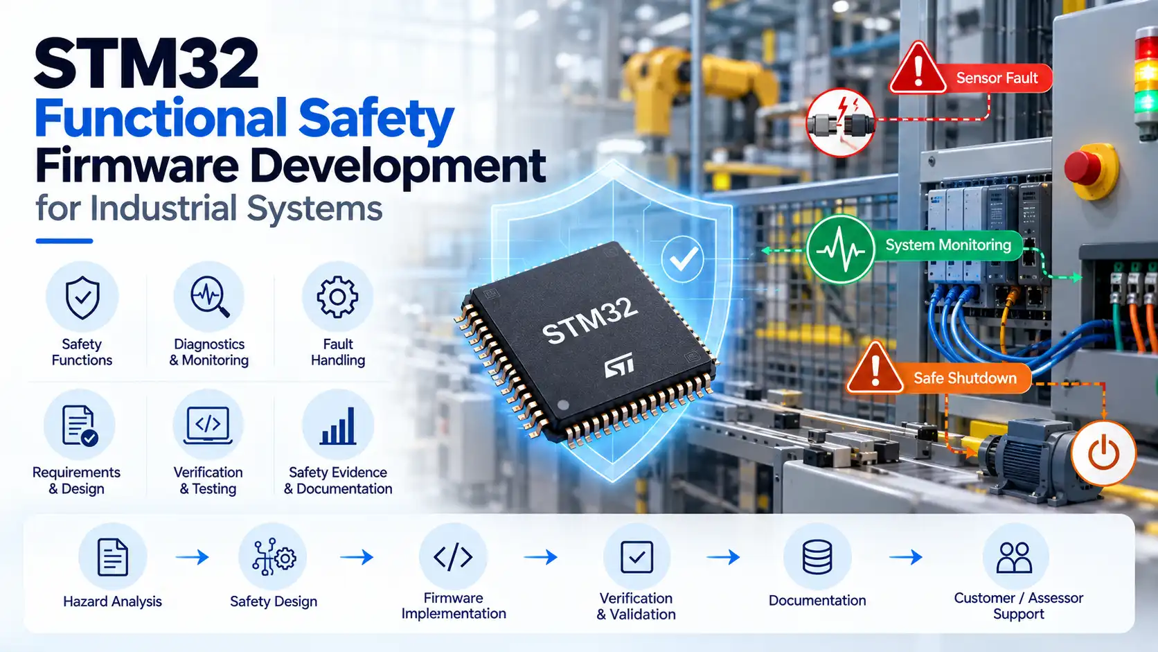
What Functional Safety Means for STM32 Firmware
Consider an electrically powered machine with a safety door that will stop any movement in a risky operation upon the opening of the door, and thus preventing the machine from restarting inadvertently.
It must also be programmed to read validated data, initiate an output action, identify any malfunction signal, and report to the user.
The machine must make it possible to reach the safe condition needed for safety operation of the machine regardless of the failure of the processor.
IEC 61508 provides the general framework for electrical, electronic, and programmable electronic safety-related systems. Machinery projects may use IEC 62061 or ISO 13849-1:2023; process-industry safety instrumented systems are addressed by IEC 61511.
The applicable standard, required risk reduction, and scope of independent assessment are established for the particular product and application. A safety function can span several devices, so firmware cannot be evaluated in isolation.
Relevant Adequate Infosoft Project Experience
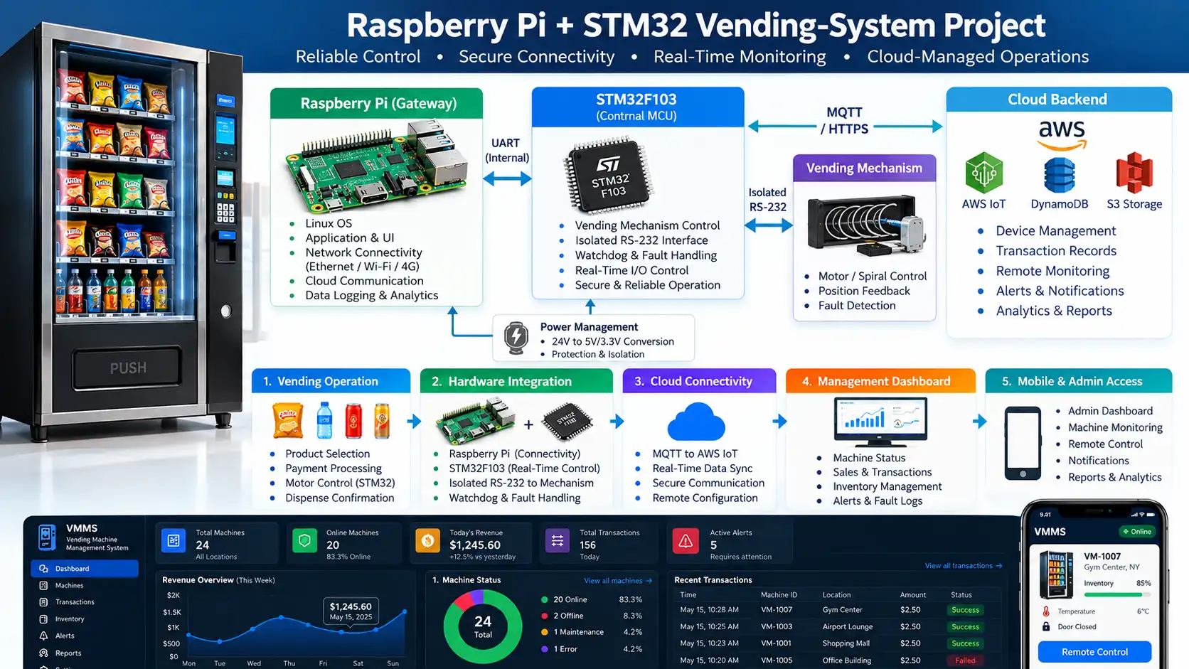
Raspberry Pi and STM32 vending-machine
The Raspberry Pi and STM32 vending machine case study that we have published includes an STM32F103 co-processor that performs time-sensitive actuation and sensors checks as well as monitoring of the watchdog, manual override, and managing of faults.
Meanwhile, the Raspberry Pi performs the duties of a higher-level processor that processes payments and is involved in connectivity.
This division of roles demonstrates a useful design principle that states that a halted user interface should not rob the system of local control. Our case study covers the tests of repeated actuation and restoration but does not guarantee compliance with IEC 61508 or achieving a SIL rating.
Read Case Study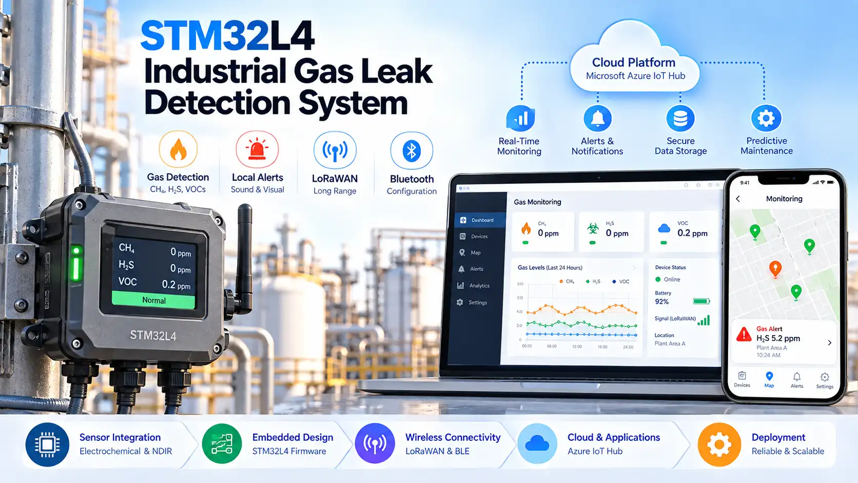
STM32 industrial gas-leak detection
In this case study of STM32 industrial gas leakage detection, considerations were paid to STM32L4 sensory processing, local alarm generation, PCB design, and remote monitoring, which is highly relevant to diagnostics and notification.
The gas leak detection instrumentation used in safety systems that are officially certified must have its own system design and assessment.
The presented case study does not show IEC 61511 certification and does not provide diagnostics coverage for this function.
Read Case StudyThese examples show experiences in STM32, controlling, sensing, and fault management. It should be noted that these examples cannot qualify as independently certified safety products. During the initiation of any new safety project, we agree on the requisite standard to follow, responsibilities of the customer, necessary proofs, and the intervention of the assessor.
Start with the Hazard and Safety Requirement
The first step in the process is to establish the project objective and the foreseeable defects and hazardous consequences, and determine the responsibilities of all subsystems.
A good safety requirement indicates what triggers the response, maximal response time, the acceptable output state, and how to reset the system. A requirement like "detect errors quickly" is not specific enough in terms of utilization in the design/testing process.
The requirement is traced back to the architecture, program code, tests, and results. In case the sensor debounce time changes, the reviewers can see which response time requirement was triggered.
The interfaces with non-safety software must be rigorously delineated, so a loss of connection should never disable the local safety feature.
The safety manager determines the required SIL (Safety Integrity Level) or PL (Performance Level) and the evidence expected. It is important to note that marketing claims cannot replace hazard analysis, calculations, or the assessor's decision.
STM32 Architecture and X-CUBE-STL Integration
ST presents a functional safety package known as X-CUBE-STL that is designed for certain STM32 devices. Included in this package are such documents as safety manual for microcontroller (MCU), failure analysis documents, and self-test libraries dealing with CPU as well as SRAM and flash memories.
However, these documents may help to support a safety case when the condition of their use correspond to the device and architecture type. According to ST, one STM32 microcontroller can be used in relation to certain SIL2 safety functions as it is one STM32 used for SIL3 functions that comprises two STM32s working in 1-out-of-2 mode.
This is architecture guidance, and not a guarantee of compliance with SIL2 or SIL3 standards for a specific product.
We select an MCU against memory, I/O, diagnostic, environmental, and safety-manual requirements. The design considers clock monitoring, watchdogs, memory tests, sensor disagreement, output feedback, and periodic checks. Every test needs a detection latency and defined reaction. A diagnostic that leaves an actuator energized has not finished the safety job.
X-CUBE-STL integration must respect timing, memory placement, the selected toolchain, and the application's scheduling model. We document the library version and device-specific assumptions, measure worst-case execution time, and test fault reactions on actual hardware.
We also identify faults that MCU self-tests cannot detect, such as a welded relay, failed transducer, or broken wire. Those require system-level measures and verification.
Firmware Services Across the Safety Lifecycle
Safety-oriented architecture
We ascertain the boundaries of the task, priorities for interruption, sequence of startup actions, transitions that guarantee safety, independent supervision, and the connection between safety and comfort features.
We ascertain the boundaries of the task, priorities for interruption, sequence of startup actions, transitions that guarantee safety, independent supervision, and the connection between safety and comfort features.
In the case of a necessity for certified or any other qualified software components, we examine its adoption and usage as per the assurance scheme of the project and not according to its brand.
Defensive embedded implementation
We implement bounded inputs, explicit state machines, controlled memory use, error handling, and observable fault reporting. The code distinguishes a process alarm from an internal diagnostic failure.
We implement bounded inputs, explicit state machines, controlled memory use, error handling, and observable fault reporting. The code distinguishes a process alarm from an internal diagnostic failure.
Clearing an alarm should not automatically re-energize machinery; restart conditions are specified separately and tested.
Diagnostic coverage and fault response
We will implement self-tests, watchdog monitoring, evidence checks, output checks, and timeout procedures to mitigate occurred fault conditions.
We will implement self-tests, watchdog monitoring, evidence checks, output checks, and timeout procedures to mitigate occurred fault conditions.
Time plays a critical role here: a RAM self-test upon the system boot-up will not cover faults emerging during the operation. The diagnostic claims should be based on failure modalities, reaction time, and evidence.
Verification and traceability
We will analyze requirements and software code, carry out the unit and integration testing, simulate faults, and get the results on the target hardware.
We will analyze requirements and software code, carry out the unit and integration testing, simulate faults, and get the results on the target hardware.
We will capture the software build, testing, simulation, output from the system, and passing criteria.
Release and maintenance
We establish configuration control, reproducible builds, change-impact review, and a firmware update and recovery strategy. An update that interrupts the device must not leave an unsafe output state.
We establish configuration control, reproducible builds, change-impact review, and a firmware update and recovery strategy. An update that interrupts the device must not leave an unsafe output state.
Field diagnostics should identify a fault without encouraging an operator to bypass the protection to resume production.
Testing the Failures That Matter
The verification plan begins with what is required to happen, when it should occur, and how it will happen. The various tests include disconnected inputs, impossible sensor readings, processor resets, blocked tasks, voltage drops, update interruptions, and communication errors.
The distance from the fault limit to output measured is also considered.
Fault injection is not without its limitations. Changing the value of a software variable does not mean that there is also a corresponding physical sensor failure and does not confirm that the program is capable of detecting random system failures.
Bench tests, hardware-in-the-loop exercises, and installation validation serve different purposes. An acceptance report should state what was tested, what remains outside scope, and which assumptions require confirmation by the system integrator.
Safety and cybersecurity also interact. Remote configuration, network commands, and firmware updates can affect safety behavior.
We define who can change setpoints, how changes are validated and logged, and what the controller does when a command is stale or unauthenticated. Cybersecurity controls support the safety design, but an authenticated network request is not by itself a safe operating condition.
Deliverables That a Reviewer Can Inspect
The expected deliverables include the firmware requirement specifications, system architecture, interfaces, source code, building process, traceability information, diagnostic reports, testing procedures, failure injection results, and release documentation.
We usually keep track of any assumptions made regarding the sensors and actuators, electricity supply, maintenance, and conditions of operation. With some assumptions missing, the tested firmware cannot be validated.
For the old STM32 controller, instead of just relabeling existing code as SIL-compliant, we should start with the gap analysis of all available information regarding requirements, hardware failure paths, libraries used, and some tests conducted before.
The main objective of the gap analysis is the identification of the things that can be kept, redesigned, or need approval from the certification authority.
Frequently Asked Questions
No. The package provides information such as details on the device and diagnostic capabilities, but does not cover the entire range of safety evaluation actions needed to certify a device according to relevant standards.
No. It can detect some stalls, but cannot diagnose every sensor, logic, memory, or output failure. Its timeout and the hardware reaction after a reset must also meet the safety requirement.
No. The required risk reduction follows the hazard assessment and applicable standard. Selecting a higher rating without a defined safety function does not resolve the engineering problem.
Provide system diagram, hazards and risk analysis, safety functions that will be provided by the product, STM32 part number, input/output circuits, timing constraints, and the target market of the project. The details will allow us to define firmware development scope.
Editorial Resources
- STMicroelectronics — X-CUBE-STL functional safety package
- STMicroelectronics — STM32 functional safety ecosystem
- IEC — IEC 61508-1:2010, general requirements
- IEC — IEC 62061:2021, safety-related machinery controls
- IEC — IEC 61511-1:2016, process-industry safety instrumented systems
- ISO — ISO 13849-1:2023, machinery safety-related control systems