















 Mean Stack Development
 Vue JS Development
 Javascript Development
 React JS Development
 Angular JS Development
 Next JS development
 Java Development
 Python Development
 Django Development
 Cherrypy Development
 C# Development
 ASP.NET Development
 NodeJS Development
 Laravel Development
 CodeIgniter Development
 Zend Development
 Ruby on Rails Development
 CakePHP Development
 PHP Website Development
 Symfony Development
 Drupal Development
 Joomla Development
 Wordpress Development
 .NET Nuke Development
 Kentico
 Umbraco
 .NET MAUI Development
 Xamarin Application Development
 iOS Application Development
 Android Application Development
 Android Wear App Development
 Ionic Development
 iBeacon Application Development
 Universal Windows Platform (UWP)
 Kotlin Application Development
 Swift Application Development
 Flutter Application Development
 PWA Application Development
 Flutter Health Tech & Wearable App Development Company
 React Native Health Tech Wearable App Development
 Offshore Software Development
 Custom Application Development
 Front-End Development
 Full Stack Development
 AI & Machine Learning
 Custom CRM Solutions
 Flask Software Development
 Electron JS Development
 ChatGPT Development
 Telemedicine App Development
 Build Smart Telemedicine Platform
 Beauty & Salon App Solutions
 Hire Workato Experts
 Magento Development
 Magento 2.0 Development
 Magento Enterprise
 Shopping Cart Development
 Prestashop Development
 Shopify Development
 Open Cart Development
 WooCommerce Development
 BigCommerce Development
 NopCommerce Development
 Virto Commerce Development
 AspDotNetStorefront Development
 .NET Application Development
 Microsoft Dynamics CRM
 VB .NET Development
 Sharepoint Migration
 ASP.NET Core Development
 ASP.NET MVC Development
 AJAX Development
 Agile Development
 Microsoft Bot
 Microsoft Blazor
 Microsoft Azure Cognitive
 HTML 5
 UI/UX Design
 Graphic Design
 Adobe Photoshop
 XML Application Development
 Cloud Computing Solutions
 Azure Cloud App Development
 AWS Development
 Google Cloud Development
 Certified AWS IoT Services Developers
 DevOps Consulting & Development
 Kubernetes Consulting & Services
 SQL Programming Development
 MySQL Development
 MongoDB Development
 Big Data
 Robotic Process Automation
 Social Media Marketing
 Search Engine Optimization
 QA Testing
 Software Testing
 Software Security
 Maintenance And Support
 I.T. Consulting Services
 Business Intelligence
 YII Development
 Data Analysis
 Alexa Skills Development
 On Demand App for Mobile repairing services
 On Demand App for Car Service Booking
 On Demand App for Cleaning Services
 On Demand App for Pharmacy
 On Demand Dedicated Developers
 On Demand Lawyer App Development







 Nuki Smart Lock
 Salto Smart Lock
 TTlock Smart Lock
 NFC App Development
 Custom IOT Enabled Smart Lock
 Smart Locker Solutions
 Hospital Smart Lock Systems
 Hotel Smart Lock Systems
 Smart Home & Office Locks
 Smart Access for Schools & Colleges
 Unloc Smart Lock Integration
 Yale & August Smart Lock Integration
 Populife Smart Lock Integration
 Smart Lock Hardware Development
 Dairy IoT Solutions
 Agri IoT & AI Solutions
 Weather & Climate Solutions
 Water & Waste Management Solutions
 RaspBerry Pi
 Firmware Software Development
 ESP 32 Software Development
 Embedded Development
 Internet of Things
 Smart IoT Development
 IoT Sensor Integration & Development Solutions
 Smart IoT System Development for HVAC
 Tuya IoT App Development
 Particle IoT SDK
 IoT Development with AI
 Smart Pet GPS Tracker
 Dairy GPS Tracking Solutions
 GPS Fleet Management Software
 Car Rental & Subscription Solutions
 Car Buy & Sell Marketplace Development
 AI-Powered Car Wash App Development
 PCB Design & Fabrication
 IoT AC Automation
 AI–IoT Painting Solutions
 IoT Wearable Hardware & App Development
 HVAC Automation & AI Control Systems
 Smart Home IoT Engineering
 AI Embedded Systems
 AI Hardware Design Service
 Advanced IoT Hardware & Firmware Development
 Device Driver Development Services
 NXP i.MX RT Firmware & Hardware Services
 Microchip PIC & AVR Development
 Hire IoT Architects
 IoT Cloud & Infrastructure Solutions
 Infineon XMC / AURIX Development Services
 Matter & Thread IoT Services
 Native IoT Mobile App Development (BLE & Wi-Fi)
 Snapdragon IoT Firmware Development
 Renesas RA/RX Firmware Services
 Silicon Labs EFR32 Development Services
 Smart Wearable App Development
 Smart IoT Meters
 Smart Healthcare Wearable App Development
 Health Care Monitoring System
 Fitness Tracking App Development
 Smart Home Automation Apps
 nRF PCB Design
 ESP32 PCB Design
 Embedded Wearables Engineers
 Rental Property Management System
 Building Management System
 Smart Lighting Development
 Infineon Semiconductor Firmware Development Services
 Custom Camera Development: Hardware, Firmware & PCB Prototyping
 Smart Security Camera SDK
 Nordic Semiconductor SDK
 Infineon SDK
 Arduino SDK
 NFC Lock Integration
 Kerong Lock Integration
 IoT & AI Solutions for Manufacturing
 Smart Inventory & Logistics Solution
 Food & Beverage Industry Solutions
 Smart Hospitality Solutions
 Smart Property Management
 Custom Smart Home IOT SDK
 Smart IoT & AI in Healthcare
 AI-Powered Security Solutions
 Smart Home Safety & AI
 Veterinary Clinic Management (AI)
 Pet Care System (AI & IoT)
 Pet Training & Adoption (AI)
 Healthcare IoT Development
 Event Management Software
 Money Remittance App
 Money Lending App Development
 Utility and Bill Payment App
 IoT Mobile App Development (Flutter & React Native)
 AI & IoT Retail Solutions
 Smart EV App Development
 Smart Solar IoT & AI Solutions
 IoT-Based Energy Systems
 Smart Energy & Utilities Solutions
 6G Solutions
 IoT Security Solutions
 AI-Powered Lottery App Development
 AI-Sports Fitness Club Management
 Travel
 Real Estate
 Medical & Healthcare
 e-Learning
 Consumer Products
 Finance
 Automobile
 Media & Entertainment
 Billing Software
 Enterprise Resource Planning (ERP)
 Augumented & Virtual Reality
 Point of Sale(POS) Development
 Learning Management System
 EV Charging Solutions
 About Us
 Partners & Certifications
 Quality Assurance
 Our Clients & Testimonials
 Development Process
 Our Products
 Social Responsibility
 Work Ethics
 Vision & Mission
 Awards
 Live Project Demos
 Contact Us
 Case Studies
 Portfolio
 Blog
Blog
STM32 Board Bring-Up, Debugging & Firmware Rescue
The board powers up, but nothing useful happens. SWD is intermittent, a peripheral returns impossible values, the watchdog resets without evidence, or Nucleo-tested firmware fails on the custom PCB. Random code changes rarely solve faults spanning hardware, startup, configuration, and timing.
Adequate Infosoft provides STM32 firmware debugging services for board bring-up, inherited code, unstable prototypes, failed migrations, and field returns.
We use reproducible evidence: rails before drivers, reset and clock before middleware, bus waveforms before assumptions, and captured fault state before edits.
Let's Work Together!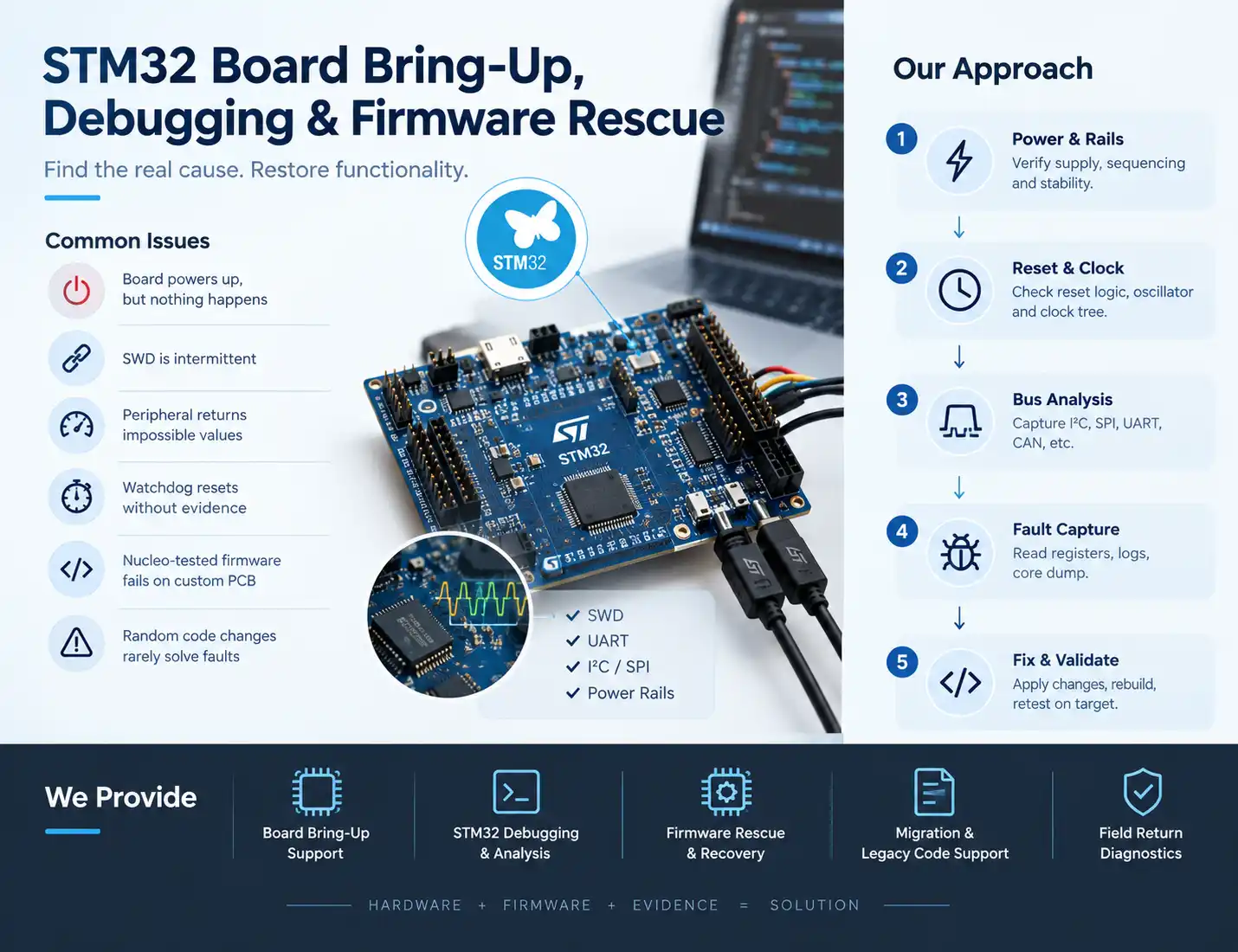
When an STM32 Project Needs Rescue
It could be that you have completed your boards without yet developing the firmware, acquired the source code incompletely, failed to reproduce the build and run into issues, or encountered sporadic in-field failures. Some symptoms may be:
ST-Link cannot find the MCU and loses the contact after reset; the unit gets stuck in the bootloader, experiences HardFaults, or keeps resetting; the external oscillator, PLL, SDRAM, QSPI, USB, Ethernet, or display does not work; I2C, SPI, UART, CAN, FDCAN, or ADC do not transfer the data properly; FreeRTOS tasks get stuck, the stack overflows, interrupts do not get fired in time; current consumption in stopping/standby is excessively high; one PCB version works while another fails at certain temperature or load; debug build behaves differently from release build; firmware updates, option bytes, or data protection trigger unit blocking.
You may turn to us for diagnosis, completion, stabilization, or production transfer.
Our Debugging Order: Establish Facts Before Theories
An efficient rescue follows dependencies. A collapsing processor supply is not an RTOS problem; a wrong vector address is not a sensor-driver problem.
| Layer | Evidence we inspect | Questions answered |
|---|---|---|
| Electrical | Rail ramp, current, ripple, reset, boot pins, clock | Is the MCU powered and released correctly? |
| Access | SWD/JTAG, device ID, option bytes, flash contents | Can the target be controlled and trusted? |
| Startup | vector table, stack, SystemInit, clocks, linker map | Does execution reach main with valid memory? |
| Peripheral | register state, bus capture, DMA and interrupts | Is configuration consistent with hardware? |
| Application | tasks, queues, heap, state machines, logs | Why does behavior fail over time or load? |
| Product | temperature, EMI, brownout, repeated cycling | Will the correction survive real operation? |
This order produces a defensible root cause, not a patch that works once.
Stage 1: Power, Reset, Clock and Debug Access
Review schematics, PCB upgrade, BOM replacement, assembly instructions, voltage and reliability check. Equipment test includes electricity channels, analog power, reference voltage decoupling, reset, BOOT arrangement, oscillators and debugging voltage.
For more complex purposes, we lower SWD speed, reset and check reset sources, and compare option bytes.
STM32CubeProgrammer reads, deletes, programs and verifies memory, controls option bytes, and connects using ST-LINK or bootloader.
Read protection, TrustZone, secure areas, OTP memory, and lifecycle settings are not usual flags. We work only with proper hardware and do not bypass control. If protection blocks restoration, we tell about safe erase and reprogramming.
Stage 2: Verify the Minimal Firmware Path
Once stable access is obtained, the minimum firmware can be executed, which verifies that it is running at the correct address, with the necessary clocks configured, GPIO state changed and certain statuses provided. This allows to distinguish between board support errors and application errors.
All functions such as booting, interrupts, memory stack, linker scripts, memory sections, boot offset, memory protection and floating-point values, clock etc. are tested. When it comes to multicore processors and TrustZone technology, the booting process, as well as security measures are checked.
Recovery through a device-specific bootloader can be performed by means of UART, USB DFU, I2C, SPI, CAN or FDCAN protocols. It is important to remember that ST's document AN2606 provides authoritative instructions on the matter; however, no assumptions can be made about other STM32 devices.
Stage 3: Capture the Crash, Reset or Freeze
A repetitive HardFault handler eliminates proof of failure. We obtain stacked registers, program counter/saved register, fault status, exception, stack pointer limits, reset reason, version, and application status. Addresses are found based on the ELF and map files of the unit concerned.
STM32CubeIDE gives the possibility of performing debugging activities such as the usage of breakpoints, checking registers and memory, disassembly, fault review, SWV tracing, and RTOS-aware debugging. Depending on the core and connections used, we can apply watchpoints, traces, counts, GPIO timing, etc. The optimization made in the release version works even if there are defects hidden by the normal debugging duration.
STM32CubeMonitor can visualize runtime variables through ST-LINK without continuously halting execution. We graph queues, sensors, memory margins, states, or fault counters and align them with electrical captures.
Peripheral, DMA and Communication Debugging
Peripheral faults cross boundaries: marginal electrical levels, wrong alternate functions, stale DMA cache data, invalid interrupt priorities, or incorrect power-up timing.
We check GPIO, pulls, power levels, clock signals, clock timing, chip selection, termination, DMA, buffer ownership, cache memory and interrupts. Logic analyzers are used to uncover wire transactions while oscilloscopes measure rise time, ringing, noise, clock quality, and analog settling.
Coverage includes ADC/DAC, timers, PWM, encoders, I2C, SPI, UART, USB, CAN/FDCAN, Ethernet, SDMMC, QSPI/OSPI, SDRAM, displays, cameras, sensors, BLE and cellular or Wi-Fi modules. The correction may combine firmware, PCB rework, and component changes.
RTOS, Low-Power and Long-Run Failures
We assess the priorities, latency caused by interrupts, critical segments, mutexes, queues, margins of the stack, fragmentation of the heap, watchdogs, DMA concurrency, and avenues of malfunction. Measurements on the real hardware are complemented by static analysis and unit testing.
The scenarios of low power for the rescue cover are the standstill/idle condition, sources of wake-up, clock recovery, leakage of GPIO, debug current, deactivation of peripherals, mode of operation of regulator, and the retention. Each condition is measured.
The long tests include sleep, communication, updates, issue of interruptions and reconnections.
From Diagnosis to a Failsafe Repair
A complete repair requires that the solution function on all installs. The defective original is kept, the investigation is versioned, board identifiers are noted, and the fault is turned into a regression test. Fixes go through review and tests on related features.
The deliverables might include a cause report, measurements, corrected code, CubeMX configuration, startup modifications, hardware recommendations, recovery steps, automated builds, testing software, manufacturing checks, and risks ranked according to severity. The residual uncertainty is pointed out plainly.
For wider implementation support, see our custom firmware development services.
Relevant STM32 Case Studies by Adequate Infosoft
These published projects demonstrate related STM32 delivery. They are not described as rescue projects; their relevance lies in systems that require disciplined bring-up, integration, measurement, and validation.
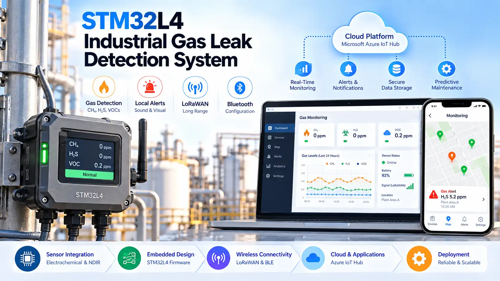
STM32L4 industrial gas-leak detection system
Adequate Infosoft has designed the STM32L4 industrial monitoring system that includes both electrochemical and NDIR sensors, as well as local alarms, LoRaWAN, bluetooth technology, and cloud support. The system is capable of demonstrating high efficiency, safety, wireless integration, and great reliability.
Read Case Study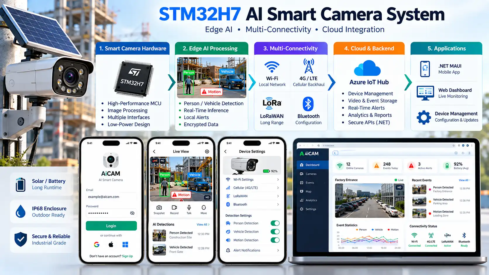
STM32H7 smart camera with multiple connectivity paths
This system combines STM32H7 control, imaging, edge-compute resources, LoRa, Wi-Fi, cellular backhaul, battery/solar power, and a .NET MAUI application. It demonstrates multi-controller integration across clocks, high-throughput interfaces, power states, and communication fallback.
Read Case Study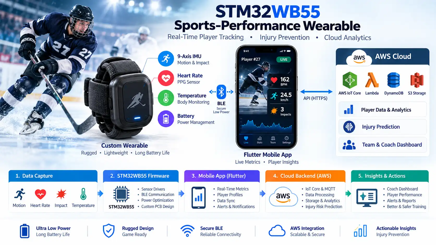
STM32WB55 sports-performance wearable
For a hockey-dedicated device worn by players, the STM32WB55 processor, motion and impact detection sensors, heart-rate and temperature sensors, BLE technology, a customized PCB developed by the engineers, battery management, and AWS services were combined with Flutter software, allowing to properly demonstrate functionalities like firmware, wireless and sensor technology usage, and efficient power consumption.
Read Case StudyRescue Your STM32 Project with Measurable Evidence
Send the STM32 part number, board revision, failure symptoms, what changed, available project files, and steps already attempted. Adequate Infosoft will propose an STM32 board bring-up or firmware debugging plan with a clear first milestone, required evidence, and practical deliverables.
Frequently Asked Questions
Most of the times, it happens due to the reset behavior, SWD configuration, option bytes, problems in power, clocking, or if the application is locked. In certain cases, physical damage or permanent anti-tamper settings could prevent recovery. Hence, we put off any assumptions about the outcome until we do actionable diagnosis.
Yes. A complete repository, reproducible build, ELF/map files and schematic help. With only a protected binary, options are limited; we will not circumvent readout protection.
Yes. In fact, we can recommend prototypes rework, modify firmware, revise schematic diagrams and PCB layouts, and carry out tests. The details of the required services depend on the board complexity and the availability of design documentation.
Editorial Resources