.NET MAUI Development
Xamarin Application Development
React Native App Development
iOS Application Development
Android Application Development
Android Wear App Development
Ionic Development
Universal Windows Platform (UWP)
Kotlin Application Development
Swift Application Development
Flutter Application Development
PWA Application Development
Hire Flutter Developers
Hire Certified React Native Developers
Flutter Health Tech & Wearable App Development Company
React Native Health Tech Wearable App Development
Offshore Software Development
Custom Application Development
Front-End Development
Full Stack Development
AI & Machine Learning
Custom CRM Solutions
Flask Software Development
Electron JS Development
ChatGPT Development
.NET Application Development
.NET Nuke Development
Microsoft Dynamics CRM
Microsoft Small Business Solution
VB .NET Development
C# Development
Sharepoint Migration
Sharepoint Development
ASP.NET Core Development
ASP.NET Development
ASP.NET MVC Development
Kentico CMS
Umbraco CMS
AJAX Development
Agile Development
Microsoft Bot
Microsoft Blazor
Microsoft Azure Cognitive
.Net Maui Healthcare Wearable App
Nuki Smart Lock
Salto Smart Lock
TTlock Smart Lock
NFC App Development
Smart Locker Solutions
Hospital Smart Lock Systems
Hotel Smart Lock Systems
Smart Home & Office Locks
Smart Access for Schools & Colleges
Unloc Smart Lock Integration
Yale & August Smart Lock Integration
Populife Smart Lock Integration
Smart Lock Hardware Development
RaspBerry Pi
Firmware Software Development
ESP 32 Software Development
Embedded Development
Internet of Things
IoT Sensor Integration & Development Solutions
Azure IOT Integration
Tuya IoT App Development
Particle IoT SDK
Hire IoT & Embedded Developers
STM32 Firmware & Hardware Development
IoT Development with AI
Dairy GPS Tracking Solutions
GPS Fleet Management Software
Car Rental & Subscription Solutions
Car Buy & Sell Marketplace Development
AI-Powered Car Wash App Development
PCB Design & Fabrication
IoT AC Automation
AI–IoT Painting Solutions
IoT Wearable Hardware & App Development
HVAC Automation & AI Control Systems
Smart Home IoT Engineering
AI Embedded Systems
AI Hardware Design Service
Advanced IoT Hardware & Firmware Development
Device Driver Development Services
Microchip PIC & AVR Development
Hire IoT Architects
IoT Cloud & Infrastructure Solutions
Infineon XMC / AURIX Development Services
Matter & Thread IoT Services
IoT Wearable Device Development
Native IoT Mobile App Development (BLE & Wi-Fi)
Snapdragon IoT Firmware Development
Renesas RA/RX Firmware Services
Smart Wearable App Development
Smart IoT Meters
Smart Healthcare Wearable App Development
Health Care Monitoring System
Fitness Tracking App Development
Smart Home Automation Apps
nRF PCB Design
ESP32 PCB Design
STM32 PCB Design
Embedded Wearables Engineers
Rental Property Management System
Smart Lighting Development
Infineon Semiconductor Firmware Development Services
Custom Camera Development: Hardware, Firmware & PCB Prototyping
In this study, a battery management system (BMS) consisting of 15-cell series has been developed for a 48 V industrial energy storage application.
Monitoring of cell voltages and temperatures, passive balancing of cells, state-of-charge and fault information transmission over CAN bus, and application of layered safety measures for protection against overvoltage, undervoltage, overcurrent, and overtemperature were among the requirements placed before the BMS developers.
The performance targets included: measurement accuracy for cell voltage of ±2 mV, measurement accuracy for temperature of ±1 °C, balancing activation threshold of 50 mV cell-to-cell difference between voltages basic data transmission speed over CAN bus of 500 kbps while using CANopen protocol in the message format.
The BMS also needed to support field calibration of current and voltage channels without firmware recompilation.
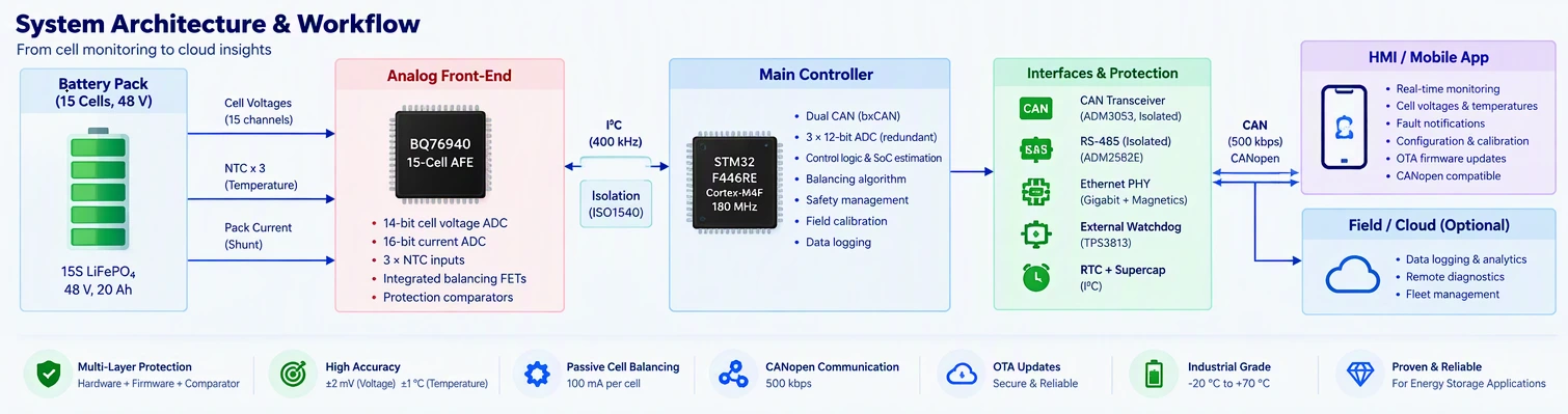
The central processing unit was the STM32F446RET6, an ARM Cortex-M4F microcontroller running at 180 MHz with 512 KB Flash and 128 KB SRAM.
This device was selected for its dual CAN controllers (bxCAN), three 12-bit ADCs, multiple timers for PWM and input capture, and sufficient computational headroom for coulomb-counting state-of-charge estimation and protection logic.
Cell voltage measuring is now performed by a special analog front-end (AFE) which does not use the internal ADC of the STM32 anymore.
In this case, we decided to use the Texas Instruments BQ76940 which not only provides a 14-bit ADC for measuring the cell voltage, but it also has a 16-bit ADC for measuring the pack current, and allows connecting three external NTC thermistors for the temperature measurement.
The BQ76940 allows connecting up to 15 series cells which exactly matches our target configuration.
The AFE communicates with STM32 using I²C with the frequency of 400 kHz and the I²C isolator (ISO1540) provides galvanic isolation between the AFE ground on the battery side and the microcontroller ground.
Voltages of each individual cell were measured differentially between the terminals of the cell using the RC filter network with one 100 ohm resistor in series and one 100 nF capacitor connected to the negative terminal of the cell forming a low-pass filter with the cut-off frequency of approximately 16 kHz.
This means that the RC filter was able to eliminate switching noise coming from the power electronic part while not introducing any additional settling error to the 1 Hz conversion rate of the AFE.
The internal multiplexer of the BQ76940 sampled all the cells in time of 1 millisecond; the STM32 was able to poll all the AFE registers every 100 milliseconds and get all voltages of 15 cells and compute the total of the pack.
Resolution of the cell's voltage was estimated to be equal to 1 mV per LSB with accuracy of ±2 mV guaranteed during the factory calibration in the temperature range of −40 °C to +85 °C.
A separate voltage divider (100 kΩ/10 kΩ) fed an STM32 ADC channel for pack-level voltage monitoring, providing redundant measurement independent of the AFE. This redundancy was a deliberate safety requirement: if the AFE failed, the STM32 could still detect gross overvoltage or undervoltage and initiate protection.
Three 10 kΩ NTC thermistors were placed at three different locations: one in the center, one at the positive terminal and one at the negative terminal.
The thermistors were wired as a voltage divider having a 10 kΩ precision resistor which has 0.1% tolerance and 25 ppm/°C sensitivity with respect to the AFE's 3.3 V power supply.
The voltage of the divider was measured by BQ76940 internal ADC and the readings were processed by STM32 taking into account Steinhart-Hart equation.
1/T = A + B·ln(R) + C·(ln(R))³
The coefficients A, B, and C have been stored in the Flash memory so that they can be updated later during calibration. The 14-bit ADC of the AFE has provided a temperature resolution of around 0.1 °C, which is above the specified maximum accuracy limit of ±1 °C.
Additionally, there was an overtemperature comparator in the BQ76940 chip that guaranteed the redundancy of the system. If any voltage across the thermistor goes below a programmed threshold value of 60 °C, the ALERT pin of the AFE is already pulled high, thus, the AFE sends a signal to the STM32 microcontroller, which will start processing actions in response to it.
The current was determined using a 1 mΩ shunt resistor that was attached to the negative line of the battery pack.
The differential voltage across the shunt was amplified by the INA240 current-sense amplifier, which has a gain of 50, thereby giving an output of 0-3.3 V with a current range of ±66 A.
The bandwidth and the gain accuracy of the INA240 ensured accurate measurement of the current during steady and transient conditions.
The output of the amplifier was picked by the ADC1 of the STM32 at a rate of once every second.
Simultaneously, the BQ76940's internal 16-bit current ADC provided an independent measurement path with a maximum error of 0.25% after customer end-of-line calibration.
The two measurements were compared in firmware; if they differed by more than 5%, a sensor fault was logged and the BMS transitioned to a degraded mode using only the AFE current reading.
Passive balancing was implemented using the BQ76940's integrated balancing FETs, which selectively connected an external bleed resistor across cells with excess charge. The external resistor value was 33 Ω, giving a balancing current of approximately 100 mA per active cell at 3.3 V. This current was sufficient to equalize a 50 mV deviation in approximately 30 minutes for a 10 Ah cell.
The balancing logic executed in the control loop with 100 ms intervals. It calculated the mean value of the voltage of all cells, not subjected to balancing, identified those which had the voltage above the mean level by over 50 mV.
The balancing process was acceptable only when the battery pack was safe: there were no existing faults, the battery pack was at temperature in the range of 10 °C to 40 °C, and the current was under 5 A.
The BQ76940's balance FETs were enabled through I²C register writes, with a maximum of four cells balanced simultaneously to limit thermal dissipation in the AFE package. Adjacent-cell balancing was prohibited to prevent unintended current paths through the measurement multiplexer.
The CAN communication utilized the bxCAN peripheral of the STM32, operational in its standard mode at a speed of 500 kbps, with a sampling point of 87.5%.
The physical level included an isolated transceiver (ADM3053), providing a voltage isolation of 2.5 kV RMS between the Battery Management System (BMS) and the vehicle/industrial CAN bus.
The bus side included a termination resistor of 120 Ω, which was connected permanently, along with fail-safe biasing resistors (390 Ω to 5 V and 1.5 kΩ to the Earth) for proper recessive levels of the bus line in case of disconnection from the bus.
The BMS transmitted three periodic CAN messages at 10 Hz, following a profile compatible with CANopen process data objects (PDOs):
| CAN ID | Content | Rate |
|---|---|---|
| 0x180 | Pack voltage, current, SoC, SoH | 100 ms |
| 0x280 | 15 cell voltages (packed, 2 bytes each) | 100 ms |
| 0x380 | 3 temperatures, fault flags, balancing status | 100 ms |
The arrangement of the message is such that it is easy to analyze by a vehicle controller or energy management system.
The voltage in the pack is transmitted in 0.1 V, the current in 0.1 A, and the state of charge in one byte (0-100%). The voltage across the cells utilizes 12-bit packing and thus is able to fit all 15 values into 30 bytes and four CAN frames.
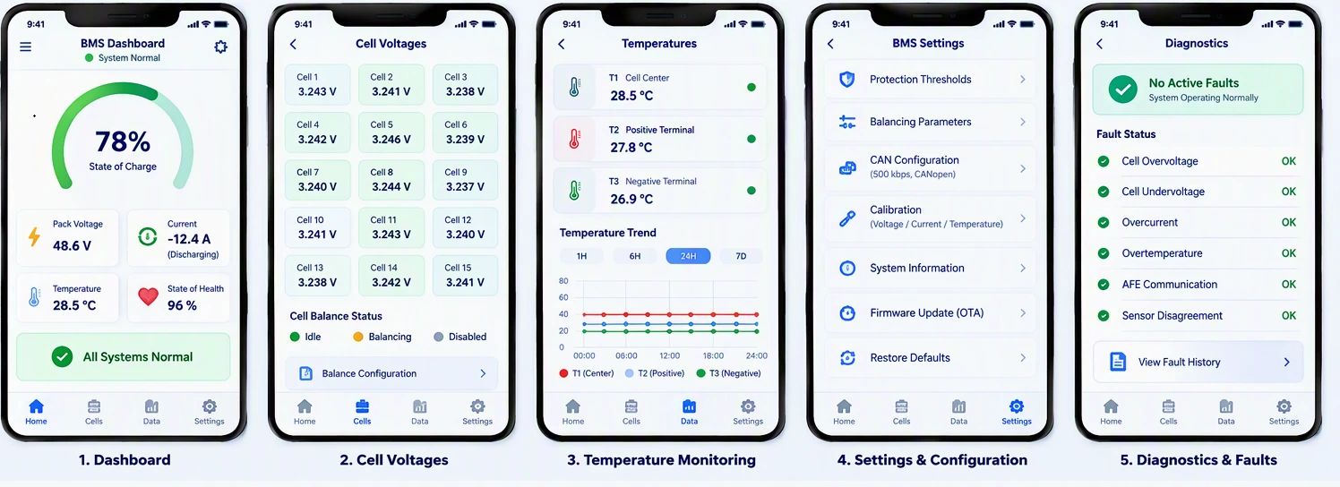
Faults were sent via event-driven messages on CAN ID 0x480, which specified the type of a fault by using a bitfield (cell overvoltage, cell undervoltage, overcurrent, overtemperature, AFE communication failure or sensor disagreement). In addition, the number of the cell that was affected and its measured value were also included.
Safety protection was implemented at three levels:
The BQ76940's internal comparators monitored cell voltages and temperatures independently of the STM32. If any threshold was exceeded, the AFE asserted its ALERT pin and could directly drive external protection MOSFETs via its CHG and DSG outputs.
The STM32's control loop checked all measured values against configurable thresholds every 100 ms. If a threshold was breached, the firmware commanded the AFE to open the protection MOSFETs and set a fault flag.
The STM32's analog comparators (COMP1/COMP2) monitored the current-sense amplifier output and pack voltage divider, providing hardware-speed response (under 1 µs) for overcurrent and short-circuit events.
The BQ76940's internal Non-volatile memory (NVM) was used for safety thresholds storage, which eliminates the need for reprogramming every time the device wakes up.
The standard threshold values are cell overvoltage of 4.25 volts, cell undervoltage of 2.50 volts, pack overcurrent of 50 A while discharging and 30 A while charging, and over-temperature of 60 °C.
The values provided are suitable for the LiFePO₄ technology and they can be modified using a CAN configuration message.
Following the occurrence of the protective event, the BMS entered the latched fault state. The recovery process called for the absence of the fault condition for 30 seconds in a row as well as a manual or CAN-commanded clearance. In the case of overvoltage and over-temperature faults, automatic recovery was forbidden so that these situations would not enter unsafe cycling.
Cell voltage channels were calibrated at end-of-line using a precision voltage source (Fluke 5520A) applied sequentially to each cell input. The STM32 recorded the AFE reading at three points (2.5 V, 3.3 V, 4.2 V) and computed a linear gain and offset correction stored in Flash. This reduced measurement error from the AFE's uncalibrated ±5 mV to the target ±2 mV.
In the present calibration, a programmable electronic load was utilized for the adjustment of the desired currents (±5 A, ±20 A, ±50 A) while the output of the INA240 was measured. Calibration was therefore performed on the basis of two points (the offset and the gain).
The current ADC of the BQ76940 was calibrated at the same time in accordance with the internal calibration registers, and the achieved accuracy of calibration was 0.25% according to the specifications of the manufacturer.
The temperature calibration was done using a highly accurate thermistor simulator (Fluke 724) to provide known resistance values for the various temperature points (0 °C, 25 °C, and 60 °C).
The values of the Steinhart-Hart coefficients were then recalculated based on the actual readings from the AFE. After that, the set coefficients were recorded in Flash memory.
During the validation of the procedure, it was verified that the value of the calibrated system was within ±0.5 °C of the reference for the entire range.
Battery management system was evaluated on 15-cell lithium iron phosphate battery pack (48 V, 20 Ah). Testing involved using battery cycler to confirm voltage measurement accuracy on all 15 channels; maximum deviation determined was 1.8 mV.
The temperature accuracy was ±0.7 °C. Balancing test revealed that the initial deviation of 120 mV was brought within 45 minutes to under 20 mV.
The Vector CANoe interface validated CAN communication. Message timing, message data packing, and fault bitfield encoding all succeeded.
Overvoltage, undervoltage, overcurrent, and overtemperature protection tests confirmed detection and clearing thresholds. A 200-hour 1C charge/discharge endurance test showed no false trigger from protection and ensured SoC estimation error well below 3%.
The BMS that is based on STM32 met all of the requirements concerning communication, accuracy, and safety for the application that was intended to be accomplished with its help.
The main conclusions made by the engineers are the importance of the dedicated AFE for precise measuring of cells, the need for independent redundant measurement paths for parameters that were of critical importance, and the significance of the final stage of the calibration applied for production achieving accuracy proved by the data sheet.
The architecture of protection built with the help of layers such as hardware, firmware, and comparator prevented having a single point of failure, which could influence the safety of the batteries, and therefore the system is successfully used in the production energy storage unit.
Client satisfaction is our ultimate goal. Here are some kind words of our precious clients they have used to express their satisfaction with our service.
I came across Adequate Infosoft while searching for an IT company to design a virtual platform for my Telemedicine business. AI helped me to make my dream project a reality.
Frederick Hess
The price and professionalism of Adequate Infosoft's project team are the most appealing aspects of working with them. The team provides weekly progress reports and responds quickly to the concerns I have.
Kim Jespersen
My team is very satisfied with the professionalism shown by the Adequate Infosoft team during the project. We are looking forward to working with them again.
Óli Freysson
I contacted AI for an Android and iOS application and I am completely satisfied with their service.
Thomas Cheah
I am very satisfied with Adequate Infosoft. very helpful, positive, and quick communication so far. I am looking forward to further cooperation.
Great experience hiring them, understood the requirements very well, and were very effective and efficient in delivering the project. I will hire them for my next project as well and also recommend them to others.
Adequate Infosoft lead development team is efficient and provides the best IT solutions. If you're looking for quick and affordable software development, Adequate Infosoft is your go-to guru!
Adequate Infosoft has stood out to be the best company for providing IT services at affordable prices. Their rapid development approach works in line with our iterative process.
David Kattah
We have worked with Adequate Infosoft for 4 years and it has been a positive experience for me and my company.
Frank Eson
Adequate Infosoft has set a benchmark with its robust product development services. Their development team is highly professional that understands the value of time.
Exceptional service! The AI team guided me through the entire procedure and made it an enjoyable experience.
Kim Jespersen
As a small business, we were most attracted to Adequate Infosoft's competitive pricing and the ability to quickly scale up or down the number of developers supporting the application.
Mr. Aaron
It was a pleasure to collaborate with Adequate Infosoft. Their development team is comprised of true experts.
Adequate Infosoft helped us get the most from Ceraphi, with smooth setup, responsive support, and practical, effective solutions.
Adequate Infosoft helped us develop our smart lock solution, including both the mobile app and web app
The Adequate Infosoft team helped us deliver a custom IoT solution for our European customers very efficiently
Smart Controls
Adequate Infosoft did a great job, helping us implement energy-efficient solutions smoothly.
Australia Health Pty Ltd
The team understood our needs and delivered quality health tech solutions on time.
Adequate Infosoft felt like a true partner, very supportive team, clear communication, on-time delivery, and quality work we genuinely trust.
With a physical presence in over 15 countries and a global footprint spanning 25+ countries, we are ready to serve you anywhere. Location, language, or culture is never a barrier, because our global team can work with you in your language. Our strong international team ensures seamless collaboration across borders We have a strong tech team, highly recognized in their domains, with extensive technical expertise.
Architect & Solution-Level Expert | Recognized Thought Leader with 8k+ LinkedIn Followers
Certified Developer | Driving AI, ML & Data Science Solutions
17+ Years in AI & IoT | 7,000+ Followers | Recognized Technology Leader
20+ Years in Tech | AI & Cloud Architect | HealthTech Innovator | 3,000+ Followers
IoT4All | IoT & Hardware Expert | Established Reputation in Europe
Technology Director at AOTC Limited, certified in CISSP, TOGAF, and SAFe. Leading technical operations across UK, Australia & New Zealand. Former Principal Integration Architect at Vodafone. Available on WhatsApp: +44 7563 407814, +61 458 765 85.
Helping SMEs Overcome Digitalization Challenges | Startup Tech Expert
AI, Life Sciences, HealthTech & Robotics Expert | 8,000+ Followers
25+ Years in Tech | Cloud Consultant | Lead Developer
SFMC Consultant & Developer
Cloud & AI Consultant
Tech Consultant • Sr. Application Developer • IoT & Hardware Expert
AI, IoT & Cloud Expert | Software Consultant
SAP Developer • Technical Consultant | ERP Solutions Specialist
Database & Network Expert • Mobile & Web Architect
Java Developer | Backend & Application Specialist
Engineer & Technology Consultant
Developer • Technical Consultant | Solutions & Strategy Expert
Technical Consultant | IT Strategy & Solutions Specialist
Technical Consultant & Developer
Cloud Solutions Expert with 17+ Years of Experience | HBIT Graduate | AI, IoT & Scalable Architecture Specialist
Lead Architect, Java Developer specializing in RESTful Services & Mobile Applications
Technical Consulting & Speaking | ANZ Region
Product Leadership & AI Architecture
Product Engineer (Python, C#, JavaScript, SQL) | Software Engineer & Speaker
Specializing in servers, virtualization, and network infrastructure
IoT Leadership | Global Operations | Digital Transformation
PMP-Certified Expert in IoT, AMI & Smart Metering
Send your message in the form below and we will get back to you as early as possible.
Your request has been sent successfully!