















 Mean Stack Development
 Vue JS Development
 Javascript Development
 React JS Development
 Angular JS Development
 Next JS development
 Java Development
 Python Development
 Django Development
 Cherrypy Development
 C# Development
 ASP.NET Development
 NodeJS Development
 Laravel Development
 CodeIgniter Development
 Zend Development
 Ruby on Rails Development
 CakePHP Development
 PHP Website Development
 Symfony Development
 Drupal Development
 Joomla Development
 Wordpress Development
 .NET Nuke Development
 Kentico
 Umbraco
 .NET MAUI Development
 Xamarin Application Development
 iOS Application Development
 Android Application Development
 Android Wear App Development
 Ionic Development
 iBeacon Application Development
 Universal Windows Platform (UWP)
 Kotlin Application Development
 Swift Application Development
 Flutter Application Development
 PWA Application Development
 Flutter Health Tech & Wearable App Development Company
 React Native Health Tech Wearable App Development
 Offshore Software Development
 Custom Application Development
 Front-End Development
 Full Stack Development
 AI & Machine Learning
 Custom CRM Solutions
 Flask Software Development
 Electron JS Development
 ChatGPT Development
 Telemedicine App Development
 Build Smart Telemedicine Platform
 Beauty & Salon App Solutions
 Hire Workato Experts
 Magento Development
 Magento 2.0 Development
 Magento Enterprise
 Shopping Cart Development
 Prestashop Development
 Shopify Development
 Open Cart Development
 WooCommerce Development
 BigCommerce Development
 NopCommerce Development
 Virto Commerce Development
 AspDotNetStorefront Development
 .NET Application Development
 Microsoft Dynamics CRM
 VB .NET Development
 Sharepoint Migration
 ASP.NET Core Development
 ASP.NET MVC Development
 AJAX Development
 Agile Development
 Microsoft Bot
 Microsoft Blazor
 Microsoft Azure Cognitive
 HTML 5
 UI/UX Design
 Graphic Design
 Adobe Photoshop
 XML Application Development
 Cloud Computing Solutions
 Azure Cloud App Development
 AWS Development
 Google Cloud Development
 Certified AWS IoT Services Developers
 DevOps Consulting & Development
 Kubernetes Consulting & Services
 SQL Programming Development
 MySQL Development
 MongoDB Development
 Big Data
 Robotic Process Automation
 Social Media Marketing
 Search Engine Optimization
 QA Testing
 Software Testing
 Software Security
 Maintenance And Support
 I.T. Consulting Services
 Business Intelligence
 YII Development
 Data Analysis
 Alexa Skills Development
 On Demand App for Mobile repairing services
 On Demand App for Car Service Booking
 On Demand App for Cleaning Services
 On Demand App for Pharmacy
 On Demand Dedicated Developers
 On Demand Lawyer App Development











 Nuki Smart Lock
 Salto Smart Lock
 TTlock Smart Lock
 NFC App Development
 Custom IOT Enabled Smart Lock
 Smart Locker Solutions
 Hospital Smart Lock Systems
 Hotel Smart Lock Systems
 Smart Home & Office Locks
 Smart Access for Schools & Colleges
 Unloc Smart Lock Integration
 Yale & August Smart Lock Integration
 Populife Smart Lock Integration
 Smart Lock Hardware Development
 Dairy IoT Solutions
 Agri IoT & AI Solutions
 Weather & Climate Solutions
 Water & Waste Management Solutions
 RaspBerry Pi
 Firmware Software Development
 ESP 32 Software Development
 Embedded Development
 Internet of Things
 Smart IoT Development
 IoT Sensor Integration & Development Solutions
 Smart IoT System Development for HVAC
 Tuya IoT App Development
 Particle IoT SDK
 IoT Development with AI
 Smart Pet GPS Tracker
 Dairy GPS Tracking Solutions
 GPS Fleet Management Software
 Car Rental & Subscription Solutions
 Car Buy & Sell Marketplace Development
 AI-Powered Car Wash App Development
 PCB Design & Fabrication
 IoT AC Automation
 AI–IoT Painting Solutions
 IoT Wearable Hardware & App Development
 HVAC Automation & AI Control Systems
 Smart Home IoT Engineering
 AI Embedded Systems
 AI Hardware Design Service
 Advanced IoT Hardware & Firmware Development
 Device Driver Development Services
 NXP i.MX RT Firmware & Hardware Services
 Microchip PIC & AVR Development
 Hire IoT Architects
 IoT Cloud & Infrastructure Solutions
 Infineon XMC / AURIX Development Services
 Matter & Thread IoT Services
 Native IoT Mobile App Development (BLE & Wi-Fi)
 Snapdragon IoT Firmware Development
 Renesas RA/RX Firmware Services
 Silicon Labs EFR32 Development Services
 Smart Wearable App Development
 Smart IoT Meters
 Smart Healthcare Wearable App Development
 Health Care Monitoring System
 Fitness Tracking App Development
 Smart Home Automation Apps
 nRF PCB Design
 ESP32 PCB Design
 Embedded Wearables Engineers
 Rental Property Management System
 Building Management System
 Smart Lighting Development
 Infineon Semiconductor Firmware Development Services
 Custom Camera Development: Hardware, Firmware & PCB Prototyping
 Smart Security Camera SDK
 Nordic Semiconductor SDK
 Infineon SDK
 Arduino SDK
 NFC Lock Integration
 Kerong Lock Integration
 IoT & AI Solutions for Manufacturing
 Smart Inventory & Logistics Solution
 Food & Beverage Industry Solutions
 Smart Hospitality Solutions
 Smart Property Management
 Custom Smart Home IOT SDK
 Smart IoT & AI in Healthcare
 AI-Powered Security Solutions
 Smart Home Safety & AI
 Veterinary Clinic Management (AI)
 Pet Care System (AI & IoT)
 Pet Training & Adoption (AI)
 Healthcare IoT Development
 Event Management Software
 Money Remittance App
 Money Lending App Development
 Utility and Bill Payment App
 IoT Mobile App Development (Flutter & React Native)
 AI & IoT Retail Solutions
 Smart EV App Development
 Smart Solar IoT & AI Solutions
 IoT-Based Energy Systems
 Smart Energy & Utilities Solutions
 6G Solutions
 IoT Security Solutions
 AI-Powered Lottery App Development
 AI-Sports Fitness Club Management
 Travel
 Real Estate
 Medical & Healthcare
 e-Learning
 Consumer Products
 Finance
 Automobile
 Media & Entertainment
 Billing Software
 Enterprise Resource Planning (ERP)
 Augumented & Virtual Reality
 Point of Sale(POS) Development
 Learning Management System
 EV Charging Solutions
 About Us
 Partners & Certifications
 Quality Assurance
 Our Clients & Testimonials
 Development Process
 Our Products
 Social Responsibility
 Work Ethics
 Vision & Mission
 Awards
 Live Project Demos
 Contact Us
 Case Studies
 Portfolio
 Blog
Blog
Infineon Hardware, PCB Design, Layout & Prototyping Services
Adequate Infosoft provides custom Infineon hardware development services including PCB design, multilayer PCB layout, embedded firmware development, rapid prototyping, and production-ready electronic product engineering.
We partner with Infineon’s advanced semiconductor platforms (AURIX™, PSoC™, XMC™, TRAVEO™ and AIROC™) for automotive electronics, industrial automation, EV systems, smart energy products, motor control, and IoT.
The scope of our engineering services encompasses schematic design, high speed printed circuit board layout (PCB), RF/wireless hardware integration, power electronics design, battery management, Controller Area Network (CAN) communications, Linux embedded software, real-time operating system (RTOS) embedded firmware, PCB assembly, conformance testing, and validation.
We assist startups, OEMs, and industrial manufacturers to accelerate the embedded design and development cycle of Infineon-based hardware and firmware solutions from concept through to mass production by delivering proven, scalable, and reliable embedded product development options.
Our Infineon Hardware, PCB Development Services
We offer complete hardware and software development services for Infineon-based products throughout the entire product development cycle. We have expertise in firmware development, PCB design, embedded software development, mobile app integration, cloud infrastructure setup, IoT connectivity and custom software solutions for Infineon Semiconductor MCUs and platforms. We power companies to develop secure, scalable and high-performance smart devices and connected systems with Infineon technologies.
The right microcontroller selection is essential for achieving the goals of any project. Our engineers can help you determine which Infineon microcontroller will provide the best combination of performance to meet your needs based on several factors:
Our engineers provide you with a thorough comparative analysis of Infineon's different families within your product category. With this information, you will select an appropriate microcontroller prior to commencing any design work.
We generate production-ready schematics designed to work with Infineon processors, covering:
- Processor connections: power supply, clock, reset and debug connections.
- Peripheral connections: ADC, PWM, timers and communications interfaces.
- Memory extension: external Flash/RAM and storage interfaces.
- Power Management: PMIC selection, DC/DC converters, LDOs for multiple voltages.
- Circuit protection: ESD protection; Overcurrent protection; Reverse polarity protection.
Designs follow Infineon's guidelines, for supply decoupling, oscillators and unused pins, to provide optimal EMC behaviour.
Infineon's AURIX™ and TRAVEO™ families operate at high frequencies, requiring meticulous PCB layout. Our layout services are guided by Infineon's official PCB design guidelines for high-speed serial interfaces (HSSI) such as Ethernet, FlexRay, and high-speed SPI.
| Service Category | Specific Offerings |
|---|---|
| Stack-up Design | 4, 6, 8+ layer boards optimized for signal integrity |
| Controlled Impedance | 50Ω single-ended, 100Ω differential pair routing |
| High-Speed Routing | DDR memory, Ethernet, USB, LVDS, MIPI |
| Power Distribution | Low-inductance PDN design, plane capacitance optimization |
| Decoupling Strategy | Optimal capacitor placement for frequencies up to 200MHz |
Infineon's design guidelines emphasize several critical principles that we strictly implement:
- Trace impedance control — High-speed traces must maintain 50Ω impedance (microstrip or stripline configuration)
- Solid ground reference — Never route high-speed signals over split planes
- Short trace lengths — Critical length calculation based on signal rise time
- Minimal vias — Layer changes introduce impedance discontinuities
- 45° bends — Never use 90° bends for high-speed signals
- Differential pair routing — Maintain consistent spacing and length matching
Infineon's leadership in power semiconductors requires specialized design expertise. By integrating SiC and GaN power devices with Infineon gate drivers and microcontrollers, we deliver high-performance, low-cost solutions for:
By integrating SiC and GaN, their power devices to the Infineon gate drivers and microcontrollers for Electric Vehicles (e.g., traction inverters, on-board chargers (OBC), DC-DC converters), Solar Inverters (i.e., high efficiency MPPT tracking and grid-tie inverters), EV fast chargers (from 50kW to 350kW of charging infrastructure), and industrial motor drive (e.g., BLDC, PMSM and induction motor control) designs, gives Infineon the ability to deliver high-performance, low-cost solutions to the users of their products.
- High-voltage SiC/GaN isolated gate driver layouts
- Analog front-end design capability for precision sensing
- EMI/EMC optimization for switching power stage designs
- Thermal management as it relates to PCB design (e.g., copper pours and thermal vias)
We offer both small-batch prototyping for testing purposes and larger-scale manufacturing for commercial release. Our rapid prototype offerings take full advantage of the Infineon Development ecosystem with the following key elements:
- Build on the Infineon Evaluation Board by adapting it into a reference design
- Make PCBs quickly (5–7 day turnaround)
- Source authentic Infineon components using authorized sources
- Assemble PCBs using automated SMD pick and place equipment for fine pitch components (TQFP, LFBGA)
- Conduct board level functional tests prior to shipping
Additional Prototyping Services
- Power on test and verify power rails
- Boundary scan to test BGA packages
- Flash appropriate firmware and perform basic functionality tests
- Environmental Testing (temp & humidity) when applicable
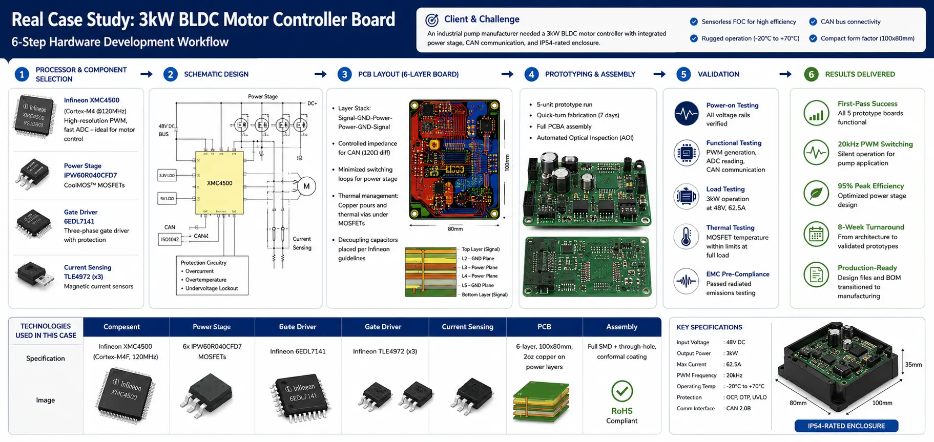
Case Study: 3kW BLDC Motor Controller Board
Our Solution: Hardware Development
- Selected Infineon XMC4500 (Cortex-M4 @120MHz) – ideal for motor control with high-resolution PWM and fast ADC
- Power stage: Infineon IPW60R040CFD7 CoolMOS™ MOSFETs
- Gate driver: Infineon 6EDL7141 – three-phase gate driver with integrated protection
- Current sensing: Three-shunt resistors + Infineon TLE4972 magnetic current sensors
- Complete motor control power stage design
- Isolated CAN transceiver (ISO1042) for industrial noise immunity
- Auxiliary power supply from 48V DC bus
- Protection circuitry: overcurrent, overtemperature, undervoltage lockout
- Layer stack: Signal-GND-Power-Power-GND-Signal
- Controlled impedance for CAN (120Ω differential)
- Power stage layout with minimized switching loops
- Thermal management: Copper pours and thermal vias under MOSFETs
- Decoupling capacitors placed per Infineon's guidelines
- 5-unit prototype run with quick-turn fabrication (7 days)
- Full PCBA assembly with SMD components
- Automated optical inspection (AOI) for quality verification
- Power-on testing: all voltage rails verified
- Functional testing: PWM generation, ADC reading, CAN communication
- Load testing: 3kW operation at 48V, 62.5A
- Thermal testing: MOSFET temperature within limits at full load
- EMC pre-compliance: passed radiated emissions testing
The five prototype boards had successful first pass operations. When these prototypes were used as replacements for existing boards, they delivered absolutely no mechanical noise (20 kHz PWM switching) during pump operation.
Peak efficiency (95% maximum peak efficiency) was achieved through optimal design of the power stage and a total of eight weeks from architecture to paper prototypes were delivered.
Production-ready designs were transitioned from the design team to manufacturing in terms of the design files and bill of materials (BOM).
| Component | Specification |
|---|---|
| Processor | Infineon XMC4500 (Cortex-M4F, 120MHz) |
| Power Stage | 6x IPW60R040CFD7 MOSFETs |
| Gate Driver | Infineon 6EDL7141 |
| Current Sensing | Infineon TLE4972 (x3) |
| PCB | 6-layer, 100x80mm, 2oz copper on power layers |
| Assembly | Full SMD + through-hole, conformal coating |
Infineon Hardware Families We Master
Our hardware expertise spans the entire Infineon portfolio. Below is every major family we work with:
| Series | Key Features | Applications |
|---|---|---|
| TC3xx | Up to 6 cores @300MHz, 16MB Flash, ASIL-D | EV traction inverters, ADAS, domain controllers, BMS |
| TC2xx | Up to 3 cores @200MHz, 4MB Flash, ASIL-D | Engine control, transmission, chassis, airbag systems |
Expertise with Hardware AURIX™:
- Package support - TQFP-80/100/144, LQFP-144/176, LFBGA-180/292
- Power supply design - VDD(1.25 V core), VDDP3(3.3 V flash), VEXT(3.3 V/5 V), VDDM(ADC supply)
- Decoupling strategy - 100nF and 330nF capacitor placement based on Infineon recommendations
- Oscillator circuit design - Separately grounded islands to reduce emissions from oscillator circuits.
- Unused pin handling - Appropriate termination to meet EMC limits (800 V/m field strength limit at 6.7 mm distance).
| Series | Key Features | Applications |
|---|---|---|
| PSoC™ 4 | Cortex-M0, CapSense®, programmable analog | Consumer HMI, touch interfaces |
| PSoC™ 6 | Dual-core M4/M0+, BLE, ultra-low-power | IoT sensors, wearables, medical devices |
| PSoC™ Edge | ML acceleration, DSP instruction set | Edge AI, predictive maintenance |
| PSoC™ Control C3 | Real-time control | Industrial motor drives, power conversion |
Our PSoC™ Hardware Expertise:
- CapSense® touch interface PCB design (sensitivity optimization)
- BLE antenna layout and impedance matching
- Low-power design for battery-operated devices
Key Applications:
Power Management and System Basis Chips
Infineon has Integrated Power Management Products including:
Technical Design Guidelines We Follow
Infineon provides comprehensive PCB design guidelines that our team strictly implements. Key principles include:
- On-board decoupling capacitors effective from 1 MHz – 200 MHz
- Above 200 MHz, plane capacitance provides decoupling
- Capacitors placed as close as possible to IC pins
- Vias placed close to capacitor pads to reduce parasitic inductance
- X7R ceramic capacitors used for temperature stability
The following signals have to be treated with caution when designing the layout of any PCBs that contain these signals:
- ERAY pins — FlexRay communications
- DAP — Debug Access Port
- Ethernet pins — High speed networking
- QSPI pins — High speed serial communications
- Exterior Clock Pins — Timing of the entire system
- SYSCLK Pin — System clock output
- Supply Pins — Power Distribution
- Need to have a continuous solid ground reference underneath all of the high-speed signals
- Don't cut the ground plane with via groups
- Ensure that return currents can flow near signal lines
- 20xH. You want to eliminate as much as 20x the thickness of the board worth of metal from the edges of power planes to limit radiated energy from the plane edges.
Infineon's guidelines specify proper handling of unused pins for EMC compliance:
| Pin Type | Recommended Termination |
|---|---|
| I/O Pins | Static low output in weakest driver mode (≤800 V/m at 6.7mm) |
| Input Pins (no pull device) | Connect to GND via 10k–1MΩ resistor (<1 pF coupling) |
| Input Pins (with pull device) | Configure as pull-up/pull-down via software |
- Separate ground island on GND layer for oscillator circuit
- Connect island at single point to main GND
- Load capacitors placed as short as possible to XTAL pins
- Ground connections of load capacitors connected to oscillator island
Start Your Infineon Hardware Project With Adequate Infosoft
If you require:
- A full Designer produced Infineon product (from idea to finished product)
- PCB layout and prototype to your current schematic
- Consulting services on processor selection and board level architecture
- Design transfer, production assistance and support for your product manufacturing
Contact Adequate Infosoft for a technical consultation. Share your requirements, and our Infineon hardware specialists will provide a detailed assessment and proposal.